Pyrotechnically actuated microvalve

a micro-valve and actuator technology, applied in the field of micro-valves, can solve the problems of large consumption of reagents and samples, high cost per analysis, and complex devi

Inactive Publication Date: 2006-06-13
COMMISSARIAT A LENERGIE ATOMIQUE ET AUX ENERGIES ALTERNATIVES
View PDF15 Cites 10 Cited by
  • Summary
  • Abstract
  • Description
  • Claims
  • Application Information

AI Technical Summary

Benefits of technology

[0011]The object of the invention is to overcome the drawbacks of state-of-the-art microvalves and, more particularly, to enable microvalves designed to be opened and microvalves designed to be closed to be achieved with a single technique. The microvalves must comprise reliable, low-consumption, inexpensive actuating means of simple and rugged design, operational only when an analysis is performed and able to tolerate storage for several years.

Problems solved by technology

This involves a large number of handling operations and consequently a non-negligible error factor, a lengthy analysis time, a large consumption of reagents and samples, and therefore a high cost per analysis.
The different types of known microvalves all present major drawbacks for applications using microfluidic components constituting microlaboratories or DNA chips.
This device is complex and contact of the fluid with the pyrotechnic material is not compatible with its use in an analysis microlaboratory in which any pollution of a sample to be analyzed must be avoided.
These different types of microactuators present the drawback of not enabling both micro-channel closing valves and opening valves to be achieved.
Such a solution is however very complicated and consequently very costly, without counting the compatibility problems this would give rise to in the course of the different manufacturing stages.

Method used


Image

  • Pyrotechnically actuated microvalve
  • Pyrotechnically actuated microvalve
  • Pyrotechnically actuated microvalve

Examples


first embodiment

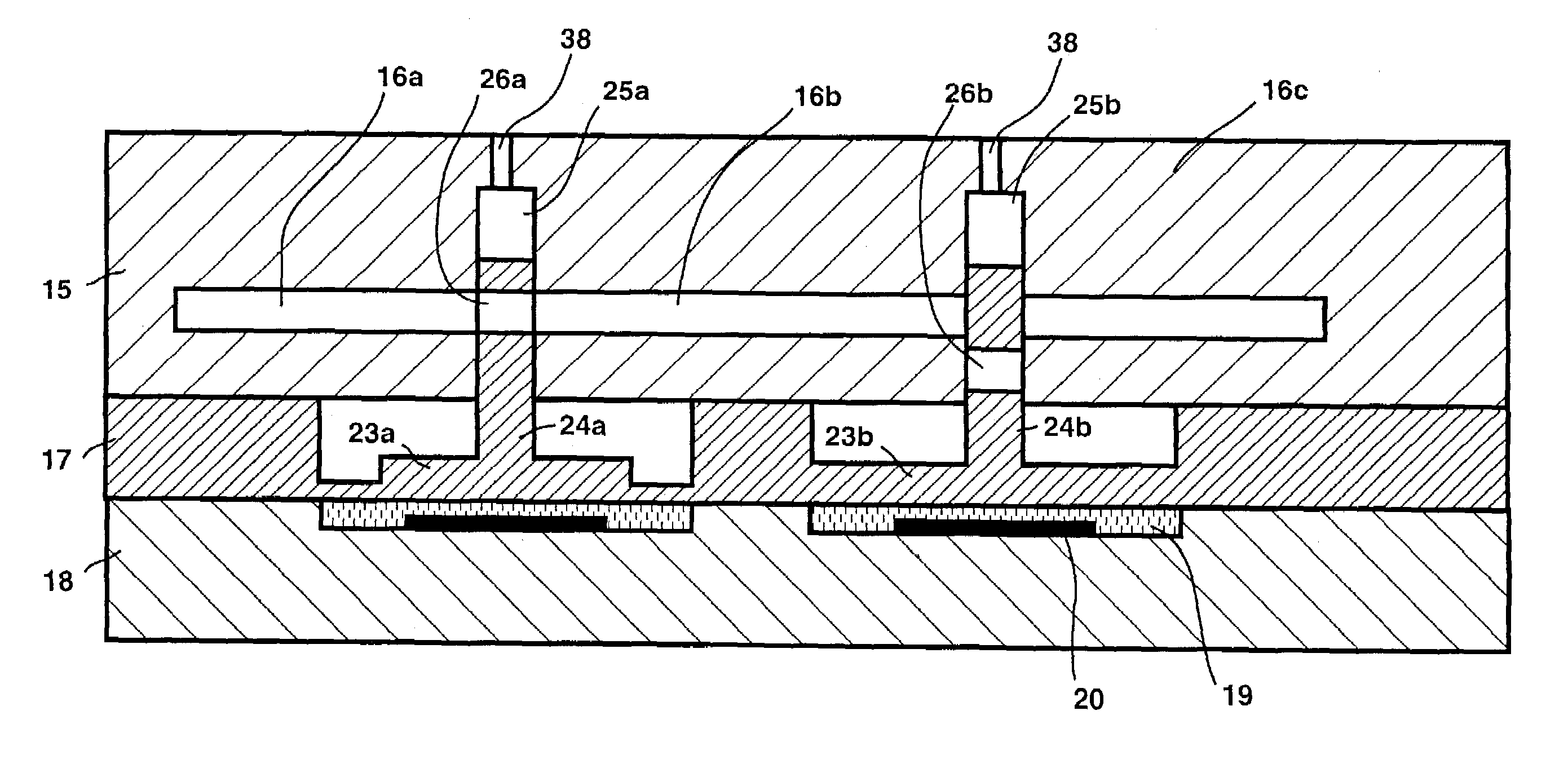
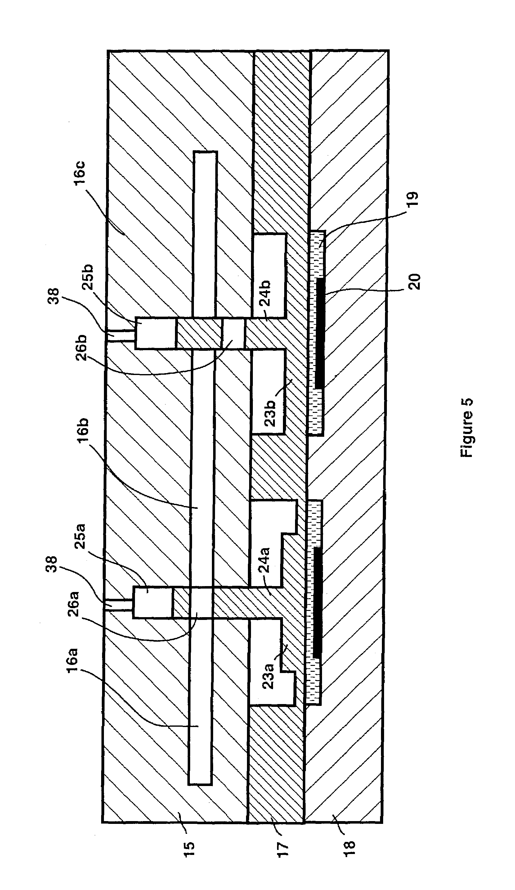
[0037]The microfluidic component of FIG. 5 comprises two microvalves according to the invention, one normally open and the other normally closed. The micro-fluidic component is formed by superposition of three cards each formed by at least one planar substrate and able to be fixedly secured by any suitable means, for example by sticking. A first card 15 comprises the microchannels 16 and / or microreservoirs and / or micoreactors constituting the microfluidic network of the component. It comprises at least a first planar substrate, preferably made of plastic material for example polymer, the microchannels being able to be etched on the surface or on an additional substrate made of plastic material, glass, silicon or quartz, added onto the plastic substrate.

[0038]A second card 17 constitutes the valve card. In FIG. 5, it is formed by a substrate wherein two microvalves are formed.

[0039]A third card 18 constitutes the actuator stage and comprises a planar substrate, made of silicon, plast...

second embodiment

[0049]a microvalve according to the invention is illustrated in FIGS. 9 and 10. As previously, the microfluidic component comprises a first card 15 comprising the microchannels 16 and / or microreservoirs and / or microreactors constituting the micro-fluidic system of the component, a valve card 17 and a third card 18 constituting the actuating stage. In this embodiment, the ends 28 of the microchannels 16 between which communication is to be established open out onto the bottom face (FIG. 9) of the planar substrate constituting the first card 15.

[0050]The valve card 17 comprises a mini-piston 29 able to move in a recess 30 of the valve card 17, in the plane of the valve card, i.e. perpendicularly to the ends 28 of the microchannels. In FIG. 10, the mini-piston 29 is joined to the periphery of the recess 30 by thin joining zones 31. A pyrotechnic charge 20 is arranged, in the card 18 constituting the actuating stage, facing one end of the recess 30, on the right of the mini-piston 29 in...


PUM


Abstract

The microvalve comprises a mini-piston moving due to the thrust of gases given off by firing of a pyrotechnic charge and comprising an aperture designed to enable communication to be established between ends of microchannels of a microfluidic component. When the ends between which communication is to be established open out onto a face of a first planar substrate, the mini-piston is formed in a second planar substrate, adjoined to the first, and comprises a part that is mobile in translation or in rotation in the plane of the second substrate. If a transverse slot is arranged between the ends of the microchannels between which communication is to be established, the mini-piston comprises a rod designed to slide in the slot and the aperture is formed by a transverse orifice formed in the rod of the mini-piston.

Description

BACKGROUND OF THE INVENTION[0001]The invention relates to a microvalve designed to enable or prevent communication of ends of microchannels of a microfluidic component under the control of a charge of pyrotechnic material.STATE OF THE ART[0002]Biological analyses make use of a succession of elementary biological reactions. Implementation thereof currently requires several workstations corresponding to different elementary stages of an analysis protocol. This involves a large number of handling operations and consequently a non-negligible error factor, a lengthy analysis time, a large consumption of reagents and samples, and therefore a high cost per analysis.[0003]To reduce costs and simplify implementation of such analyses, it has been proposed to integrate all the stages of the analysis protocol in a single microsystem. Microtechnologies make it possible to achieve micropumps, microvalves, micromotors, microfilters and mixers able to be integrated in a microfluidic device comprisi...

Claims


Application Information

Patent Timeline
Patent Type & Authority Patents(United States)
IPC IPC(8): F16K17/14B81B1/00F15B15/19F15C5/00F16K99/00
CPCB81B1/00F15B15/19F16K99/0001F16K99/0067F16K99/0011F16K2099/008F16K2099/0076F16K2099/0078Y10T137/1647Y10T137/2224Y10T137/1624
Inventor DELAPIERRE, GILLES
Owner COMMISSARIAT A LENERGIE ATOMIQUE ET AUX ENERGIES ALTERNATIVES
Why Eureka
Try Eureka