Discharge valve mechanism for variable displacement compressor

a compressor and variable displacement technology, applied in the direction of machines/engines, positive displacement liquid engines, liquid fuel engines, etc., can solve the problems of overcompression loss, inability to compress refrigerant to excess, and difference diminishing, so as to prevent the rise in cost, improve the operating efficiency of compressors, and improve the operating efficiency. the effect of the operating displacemen

Inactive Publication Date: 2006-06-13
DAIKIN IND LTD
View PDF32 Cites 9 Cited by
  • Summary
  • Abstract
  • Description
  • Claims
  • Application Information

AI Technical Summary

Benefits of technology

[0015]In the arrangement of the first aspect of the present invention in which the discharge openings (29a, 29b) are placed in the open or closed state by means of the plate-like valve element (41) which is a reed valve, the discharge openings (29a, 29b) are scatteredly formed between the base end side and the leading end side of the valve element (41), thereby making it possible to make the opening area of the discharge openings (29a, 29b) relatively large while maintaining the width of the valve element (41) at the same level as conventional. Stated another way, with this construction, there is no need to increases the size of the valve element (41) itself. Accordingly, since the opening area of the discharge openings (29a, 29b) is large, this makes it possible to prevent an excessive increase in discharge resistance, even during the large-displacement operation of the compression mechanism (20). Besides, since the valve element (41) is small in size and superior in opening / closing response, this makes it possible to prevent the occurrence of overcompression.
[0044]Finally, in accordance with the tenth aspect of the present invention, it is possible to realize the operation / working-effect of the ninth aspect of the present invention by just making the two reed valves (41A, 41B) different in thickness from each other. This makes it possible to simplify the structure of the discharge valve mechanism (40), thereby preventing the rise in costs.

Problems solved by technology

As a result, the aforesaid pressure difference diminishes, thereby causing the reed valve to carry out an operation of placing the discharge opening in the closed state.
However, there is an overcompression loss problem with the above-mentioned discharge valve mechanism.
This results in compressing a refrigerant to excess in the compression chamber.
On the contrary, if the lift amount of the reed valve is increased, this causes lags in closing the valve element.
Accordingly, there is the possibility that a volumetric efficiency drop occurs.
On the other hand, if the opening area of the discharge opening is increased, the reed valve, too, increases in size and its mass increases.
This may result in a valve opening response drop causing an overcompression loss.
This produces a new problem that the efficiency of the compressor falls off (re-expansion loss).
If the opening area of the discharge opening is increased, this results in increasing the amount of high pressure refrigerant remaining within the discharge opening.
Accordingly, the amount of refrigerant which expands in the compression chamber after discharge becomes greater and, as a result, there occurs a drop in compression efficiency.
However, even the use of a poppet valve may produce some problems.
This presents overcompression loss problems.
If such a valve element is used at a large flow rate, the velocity of flow increases because of lift amount insufficiency and opening area insufficiency.
This results in an increase in discharge resistance, thereby producing overcompression losses.
In addition, the flow velocity becomes slower and, as a result, the level of pressure acting on the valve element falls off.
Consequently, the response during the opening operation deteriorates.

Method used


Image

  • Discharge valve mechanism for variable displacement compressor
  • Discharge valve mechanism for variable displacement compressor
  • Discharge valve mechanism for variable displacement compressor

Examples


first embodiment

of the Invention

[0056]Hereinbelow, a first embodiment of the present invention will be described in detail with reference to the drawings.

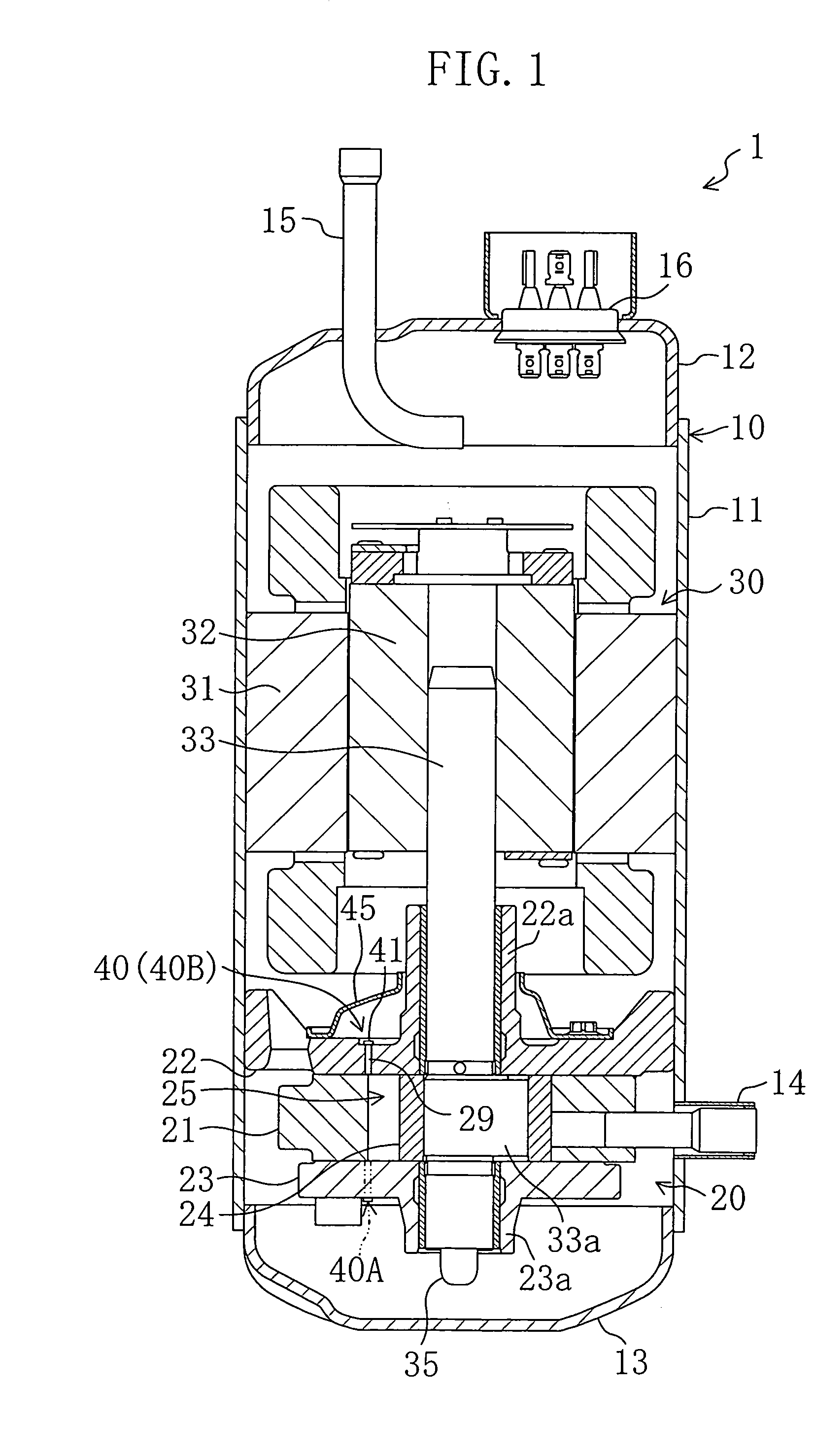
[0057]The first embodiment relates to a compressor (1) of a rotary piston type. Referring to FIG. 1, the compressor (1) comprises a casing (10) in which there are disposed a compression mechanism (20) and an electric motor (drive mechanism) (30) for activating the compression mechanism (20). The compressor (1) is of a fully closed type. When the compression mechanism (20) is powered by the electric motor (30), the compressor (1) sucks in a refrigerant and compresses it. The refrigerant compressed is discharged out of the compressor (1), and circulates in a refrigerant circuit.

[0058]The casing (10) comprises a cylindrical main body part (11) constituting a peripheral wall of the casing (10), and end plates (12, 13) fixedly secured to upper and lower ends of the main body part (11), respectively. In addition, both of the compression mechanism (20) a...

modification example

of the First Embodiment

[0083]Referring to FIG. 4(a) which illustrates an example of the valve element (41), the small-width part (41a) is formed which is situated between a portion of the valve element (41) corresponding to the first discharge opening (29a) and a portion of the valve element (41) corresponding to the second discharge opening (29b). Alternatively, as shown in FIG. 4(b), the valve element (41) may be formed into such a shape that it includes a small-width portion (41b) corresponding to the first discharge opening (29a). This arrangement also enables the leading end portion (41b) of the valve element (41) corresponding to the first discharge opening (29a) to easily bend. As a result, the first discharge opening (29a) is quickly placed in the open state during the small-displacement operation, thereby achieving high-response operations. In addition, both the discharge openings (29a, 29b) are placed in the open state during the large-displacement operation. Accordingly, ...

second embodiment

of the Invention

[0084]A second embodiment of the present invention is an example which differs from the first embodiment in that the discharge valve mechanism (40) has a different structure.

[0085]The discharge valve mechanism (40) of the second embodiment comprises a first valve mechanism (40A) disposed on the rear head's (23) side (as indicated by virtual line of FIG. 1), and a second valve mechanism (40B) disposed on the front head's (22) side.

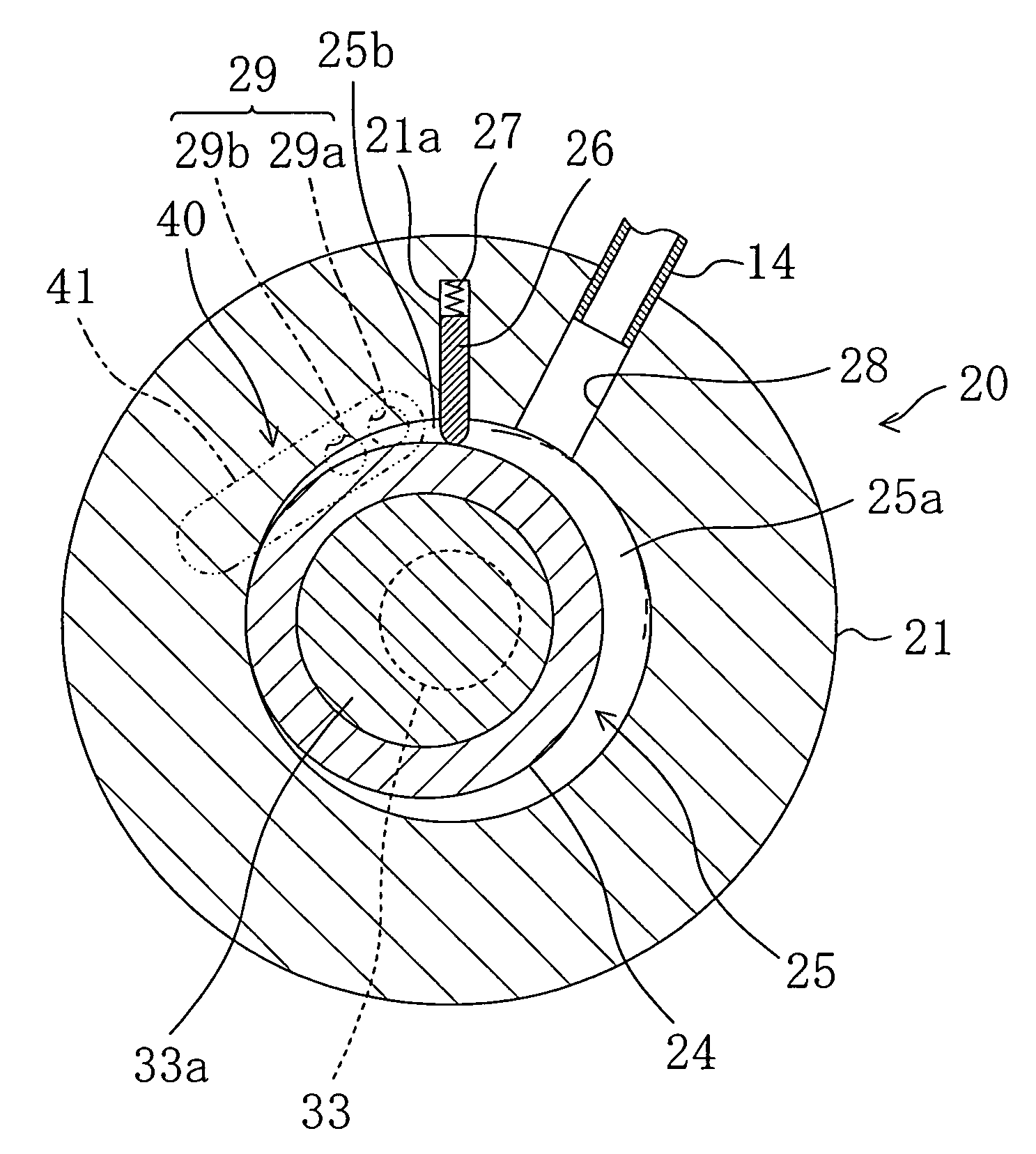
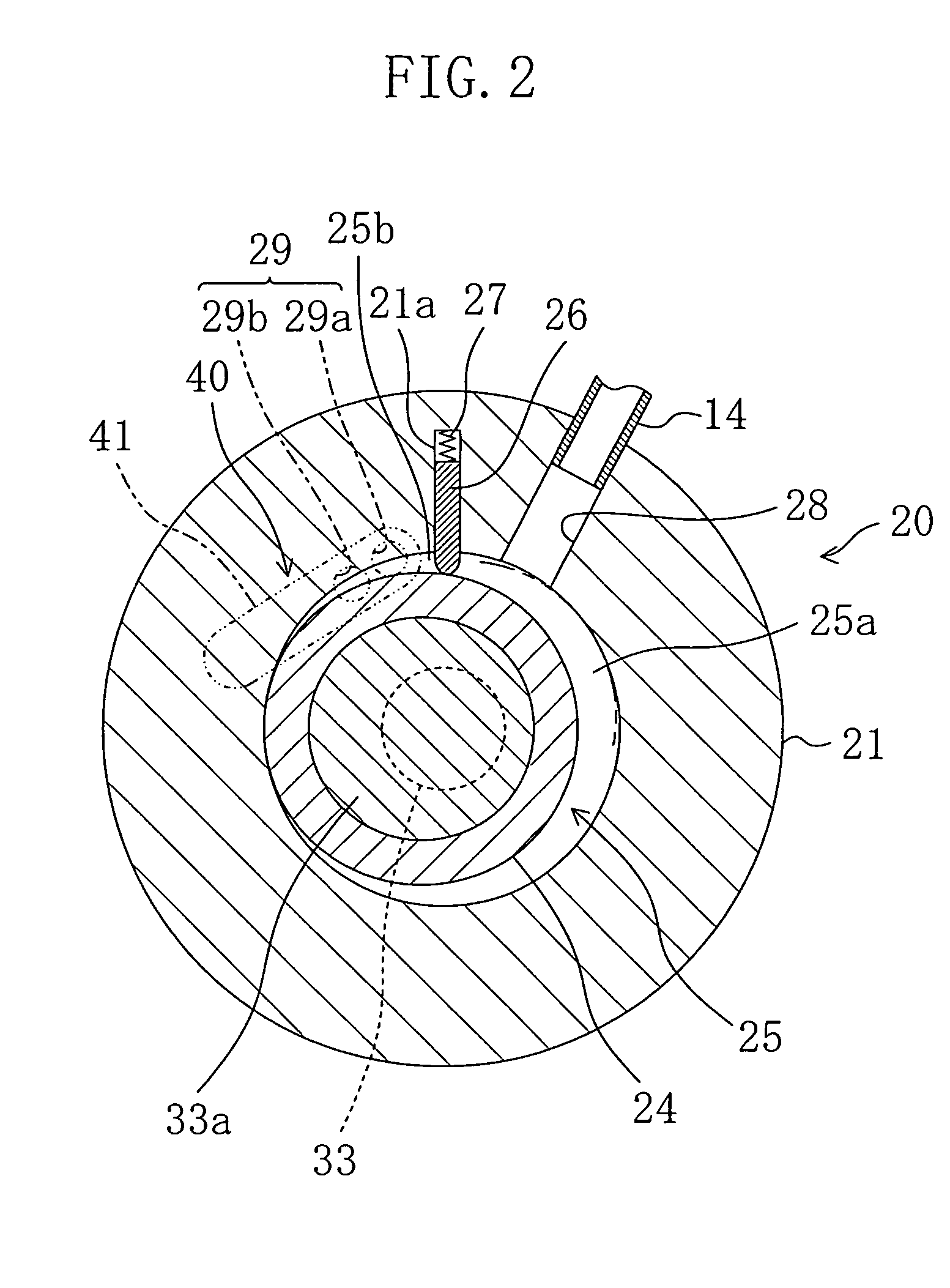
[0086]As shown in FIG. 6, in the second embodiment, the first discharge opening (29a) is formed in the rear head (23), and the first valve mechanism (40A) is configured so that the first discharge opening (29a) is placed in the open or closed state by a first valve element (41A) which is a reed valve. In addition, as shown in FIG. 5, the second discharge opening (29b) is formed in the front head (22), and the second valve mechanism (40B) is configured so that the second discharge opening (29b) is placed in the open or closed state by a secon...


PUM


Abstract

A discharge valve mechanism has a plurality of discharge openings. The discharge openings are placed in an open or closed state by a plate-like valve element. Each of the discharge openings is formed at a respective location between a base end side and a leading end side of the valve element. The number of discharge openings to be placed in the open state is varied depending on the pressure and the flow rate of gas refrigerant discharged from a compression chamber.

Description

TECHNICAL FIELD[0001]The present invention relates to a compressor and particularly to a structure for a discharge valve mechanism which is mounted at a discharge opening of a compression mechanism.BACKGROUND ART[0002]Compressors, such as rotary compressors, are well known devices used typically for compressing refrigerant in a refrigerating apparatus having a vapor compression refrigerating cycle refrigerant circuit. A conventional rotary compressor comprises a closed-type casing in which there are mounted a compression mechanism and an electric motor operable to activate the compression mechanism.[0003]The compression mechanism includes a cylinder and a piston which rotates or revolves in an eccentric motion while substantially making contact with an inner peripheral surface of the cylinder. Defined between the cylinder and the piston is a compression chamber. A blade, mounted in the compression chamber, divides the compression chamber into two parts, i.e., a low pressure side (su...

Claims


Application Information

Patent Timeline
Patent Type & Authority Patents(United States)
IPC IPC(8): F16K15/00F04B39/10F04C29/12
CPCF04B39/1066F04C29/128F04B39/1073Y10T137/7839Y10T137/7892Y10T137/784Y10T137/7891F16K15/162F04C29/00F04B39/10F16K15/161
Inventor SHIBAMOTO, YOSHITAKAHIGASHI, HIROFUMIASANO, YOSHINORISHIMIZU, TAKASHIHORI, KAZUTAKA
Owner DAIKIN IND LTD
Why Eureka
Try Eureka