Sealing element for a regenerative heat exchanger

a heat exchanger and sealing element technology, applied in the field of heat exchange technology, can solve the problems of reducing the thermal affecting the operation efficiency of seals, and affecting the operation efficiency of heat exchangers, and achieve the effect of greater operating efficiency

Inactive Publication Date: 2006-06-13
PARAGON TECH
View PDF6 Cites 9 Cited by
  • Summary
  • Abstract
  • Description
  • Claims
  • Application Information

AI Technical Summary

Benefits of technology

[0011]The aforementioned needs may be satisfied by the present invention, which relates to a seal assembly that is used to seal the angular sectors of a regenerative heat exchanging apparatus and prevent leakage between the hot gas conduit or exhaust conduit and the cold air conduit or intake conduit. The seal is advantageously configured to provide greater operating efficiency to a heat exchanging apparatus by ensuring positive contact between the heat exchanging body of a heat exchanger and the surfaces dividing the hot gas exhaust conduit and the cold air intake conduit and the sealing surfaces during relative movement therebetween even when exposed to harsh operating conditions and thermal distortion.
[0012]In one embodiment, a regenerative heat exchanging device comprises a plurality of radial and axial sector plates positioned so as to define an intake conduit and an exhaust conduit, wherein the intake conduit receives cool air so as to provide air to a power plant, and wherein the exhaust conduit receives heated gases that are exhausted from the power plant A rotor is attached to the plurality of radial and axial sector plates so as to rotate with respect thereto about an axis, wherein the rotor includes one or more heat absorbing sections that are alternatively rotated through the exhaust conduit and the intake conduit so that heat is absorbed in the exhaust conduit and is thereby transferred to the cool air in the intake conduit. The regenerative heat exchanging device has at least one seal having an outer edge, the at least one seal being mounted on an outer surface of the rotor so that the outer edge makes contact with an inner surface of the plurality of sector plates during rotation of the rotor so as to reduce the leakage of heat energy between the intake conduit and the exhaust conduit, wherein the at least one seal is deformable in a first direction that is opposite the direction of relative movement between the at least one seal and the inner surface in response to the outer edge of the at one seal making contact with the inner surface, and wherein the seal is simultaneously biased in a second direction opposite the first direction so that the outer edge of the at least one seal remains in contact with the inner surface over a range of distances between the rotor and the sector plate while the at least one seal rotates past the inner surface of the plurality of sector plates. A support member further reinforces the seal so as to inhibit damage to the seal during deformation of the seal in the first direction.
[0013]In another embodiment, a regenerative air preheater comprises an outer housing defining a first conduit and a second conduit, a heat exchanging body within the outer housing, the heat exchanging body configured to rotate with respect to the outer housing so that portions of the heat exchanging body are cyclically exposed to the first conduit and second conduit, and at least one seal located between the outer housing and the heat exchanging body, the seal including a mounting section connected to the heat exchanging body, a sealing section having a substantially straight outer edge that is contacting the outer housing, a means for resiliently and rotationally deflecting the seal in a direction opposite to a direction of rotation of the heat exchanging body so that the sealing section maintains contact with the outer housing over a range of distances between the heat exchanging body and the outer housing, and a means for reinforcing the seal in a manner so as to reduce over-flexing of the sealing section when the seal is deflected during rotation.
[0014]In yet another embodiment, a seal assembly for a regenerative preheater having a housing and a heat exchanging body that rotate with respect to each other in a first direction and define an interface therebetween comprises a seal member that is adapted to be interposed between the heat exchanging body and the housing so as to be positioned within the interface therebetween, wherein the seal member includes a deformable biasing section whereby the seal when in physical contact with at least a portion of both the housing and the heat exchanging body resiliently deforms in a second direction opposite the first direction of rotation between the housing and the heat exchanging body but is biased in the first direction, and a reinforcing member interposed between the housing and the heat exchanging body, wherein the reinforcing member is positioned with respect to the seal member so as to reinforce the seal member when the seal member is deformed in the first direction to thereby inhibit damage to the seal member as a result of the deformation.

Problems solved by technology

As is also known in the art, leakage between the hot gas conduit and the cold air conduit reduces the thermal efficiency of heat exchangers.
Unfortunately, conventional seals have many disadvantages.
For example, seals are typically exposed to harsh operating conditions, such as erosive fly ash and soot.
As the heat exchanging body moves with respect to the housing or vice versa, the seals are also exposed to mechanical abuse because the seals are positioned to maintain sliding contact with the sealing surfaces.
Consequently, the seals wear down quickly.
Further, the high operating temperatures of the heat exchanging apparatus expose the seals to thermal stresses which often cause the seals to warp.
The high operating temperature also causes thermal distortions in the shape of the structural members of the heat exchanging apparatus, such as the housing and center shaft.
The distortions in the shape of the seals and the structural members affects the clearance between the seals and the sealing surfaces, often resulting in leakage paths between the hot gas conduit and the cold air conduit.
This particular situation typically reduces the thermal efficiency of the heat exchanging apparatus and also reduces the overall efficiency of the system.
Conventional seal designs do not adequately address these problems.
However, such seals are not very flexible and often lose contact with the sealing surface when the structural members of the heat exchanging apparatus thermally distort.
However, such seals hold up poorly to corrosion and mechanical abuse.
However, such seals may fracture or break when flexibly responding to torque stress loads that are produced by rotation of the heat exchanging body with respect to the outer housing of the heat exchanger.
As a result, stress fractures may allow gas leakage between conduits.

Method used


Image

  • Sealing element for a regenerative heat exchanger
  • Sealing element for a regenerative heat exchanger
  • Sealing element for a regenerative heat exchanger

Examples


Embodiment Construction

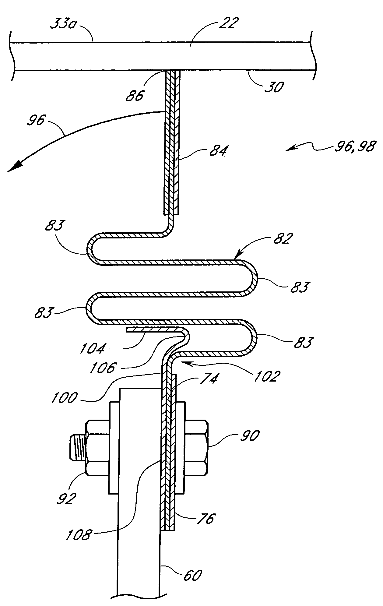
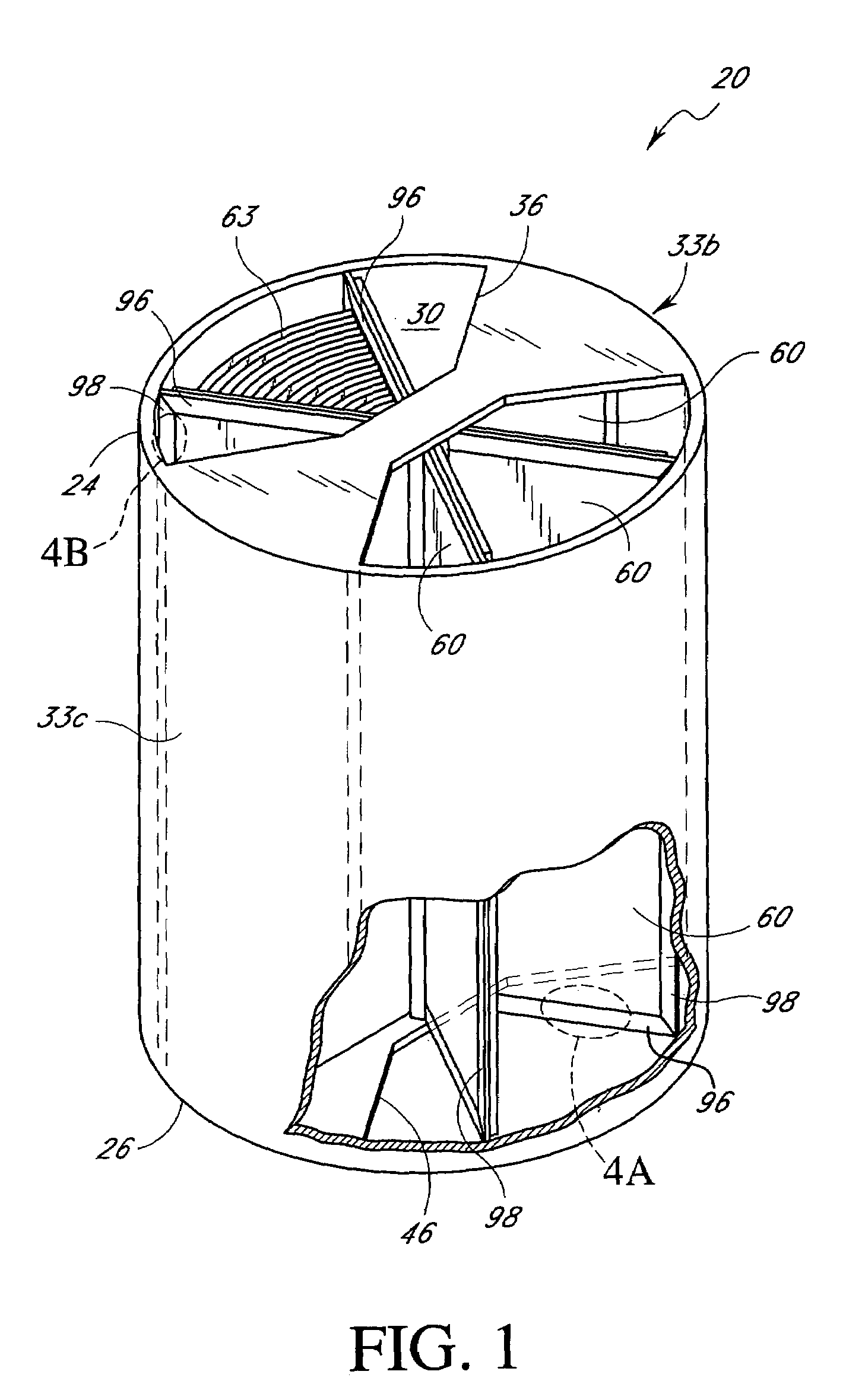
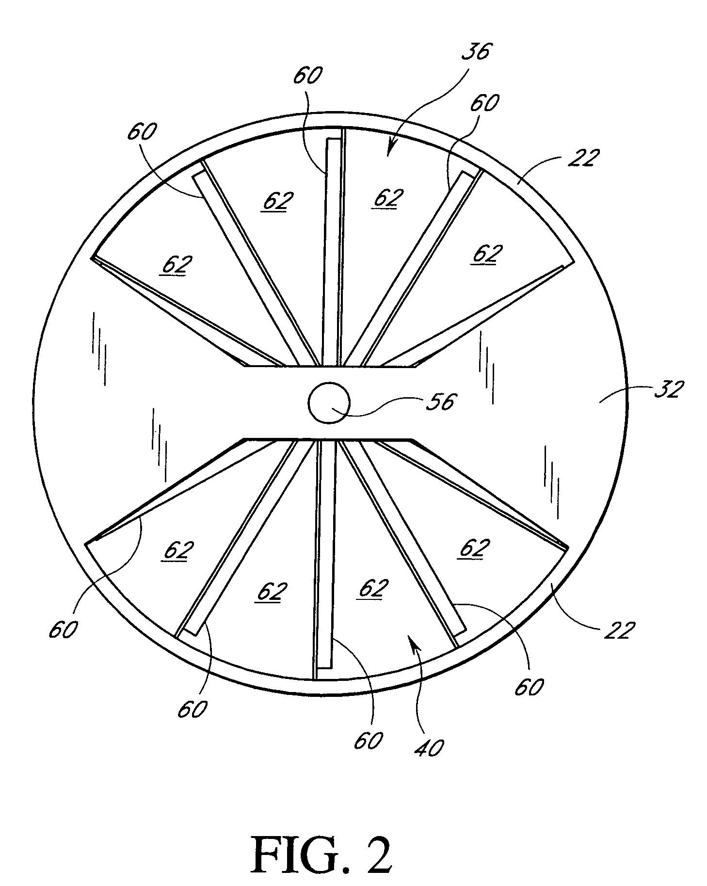
[0022]Reference will now be made to the drawings wherein like numerals refer to like parts throughout. FIG. 1 is a perspective view of one embodiment of a regenerative heat exchanging apparatus 20 in which a plurality of improved seal assemblies 96, 98 having at least one reinforcing support member (shown in FIGS. 4A, 4B, 5A, and 5B) is used. FIG. 2 illustrates a top view of the heat exchanging apparatus 20 of FIG. 1. The heat exchanging apparatus 20 includes an outer housing 22 that has a substantially cylindrical shape. The outer housing 22 has a top end 24 and a bottom end 26. As used herein, the words “top” and “bottom” are with respect to the drawings and are not intended to limit the scope of the invention. In one aspect, the heat exchanging apparatus 20 may comprise a generally known Ljungstrom™-type Air Preheater. In another aspect, the heat exchanging apparatus 20 may comprise a Rothemuhle®-type Regenerative Air Preheater, as described below. For purposes of further descrip...


PUM


Abstract

Disclosed is an improved sealing element for a regenerative heat exchanging apparatus, such as a Ljungstrom™-type or a Rothemuhle™-type Preheater. The sealing element is mounted to a radial wall to provide a secure seal between the radial wall and an outer housing of the heat exchanging apparatus and prevent leakage between the hot gas conduit and cool air conduit. In one embodiment, the sealing element includes a reinforced mounting strip that is used to mount the sealing element to the radial wall. The sealing element also includes a sealing strip that maintains a sealing contact between the radial wall and outer housing and a support member that inhibits over-flexing of the sealing element. A set of bellows is positioned on the sealing element to provide the sealing element with flexibility and resiliency so that the sealing element maintains contact with the sealing surface even when the heat exchanging apparatus experiences warping and / or distortion from thermal stress.

Description

RELATED APPLICATIONS[0001]This application is a continuation application of U.S. patent application Ser. No. 10 / 178,061, filed Jun. 19, 2002, now U.S. Pat. No. 6,789,605 and claims the benefit of U.S. Provisional Application No. 60 / 370,952, filed on Apr. 8, 2002, entitled “SEALING ELEMENT FOR REGENERATIVE HEAT EXCHANGER” which are hereby incorporated in their entirety herein.BACKGROUND OF THE INVENTION[0002]1. Field of the Invention[0003]The present invention relates to heat exchange technology and, in particular, relates to an improved sealing component that may be used to reduce leakage between a hot gas conduit and a cold air conduit of a regenerative heat exchanging system.[0004]2. Description of the Related Art[0005]Conventional regenerative heat exchangers are used to provide preheated air to heavy machinery, such as a fuel burning power plant and may be used with various types of machinery that exhausts hot gas and operates more efficiently when supplied with preheated air, s...

Claims


Application Information

Patent Timeline
Patent Type & Authority Patents(United States)
IPC IPC(8): F23L15/02F28D19/04
CPCF28D19/047F23L15/02Y02E20/34
Inventor KASER, JACKIE L.
Owner PARAGON TECH
Why Eureka
Try Eureka