
Multi-directional conveyor

a conveyor and multi-directional technology, applied in the direction of conveyor parts, mechanical conveyors, transportation and packaging, etc., can solve the problems of not being able to carry items on the current conveyor belt, and how to easily convey objects from one poin

Inactive Publication Date: 2006-06-13
CHAN EDMUND
View PDF3 Cites 17 Cited by
  • Summary
  • Abstract
  • Description
  • Claims
  • Application Information

AI Technical Summary

Benefits of technology

"The invention is a conveyor apparatus that allows objects to be transported in multiple directions. It also allows multiple trays to travel in an evenly spaced horizontal orientation regardless of the angle of change in the conveyor's plain. Additionally, it allows the trays to remain stable during changes in angular orientation in the conveyor's plain. The conveyor apparatus includes conveying belts, sprockets, a sprocket holding frame, a gear reduced drive motor, and the trays attached to the conveying belts by outwardly facing horizontal pins that are capable of rotating within corner blocks that are affixed to the trays. The conveying belts have evenly spaced apertures that accommodate the sprockets, and the drive motor powers the sprockets that are rotatably pinned to the frame, causing the belts to be driven in a linear fashion. The conveyor apparatus can change its angular orientation according to the spatial relationship of one sprocket to another."

Problems solved by technology

An Age old problem is how to easily convey objects from one point to another.
However there is a deficiency in the prior art in that current conveyor belts can not carry items so that they remain in a constant horizontal orientation even when the belt is caused to change its angle in the vertical plain.

Method used


Image

  • Multi-directional conveyor
  • Multi-directional conveyor
  • Multi-directional conveyor

Examples


Embodiment Construction

[0012]Detailed descriptions of the preferred embodiment are provided herein. It is to be understood, however, that the present invention may be embodied in various forms. Therefore, specific details disclosed herein are not to be interpreted as limiting, but rather as a basis for the claims and as a representative basis for teaching one skilled in the art to employ the present invention in virtually any appropriately detailed system, structure or manner.

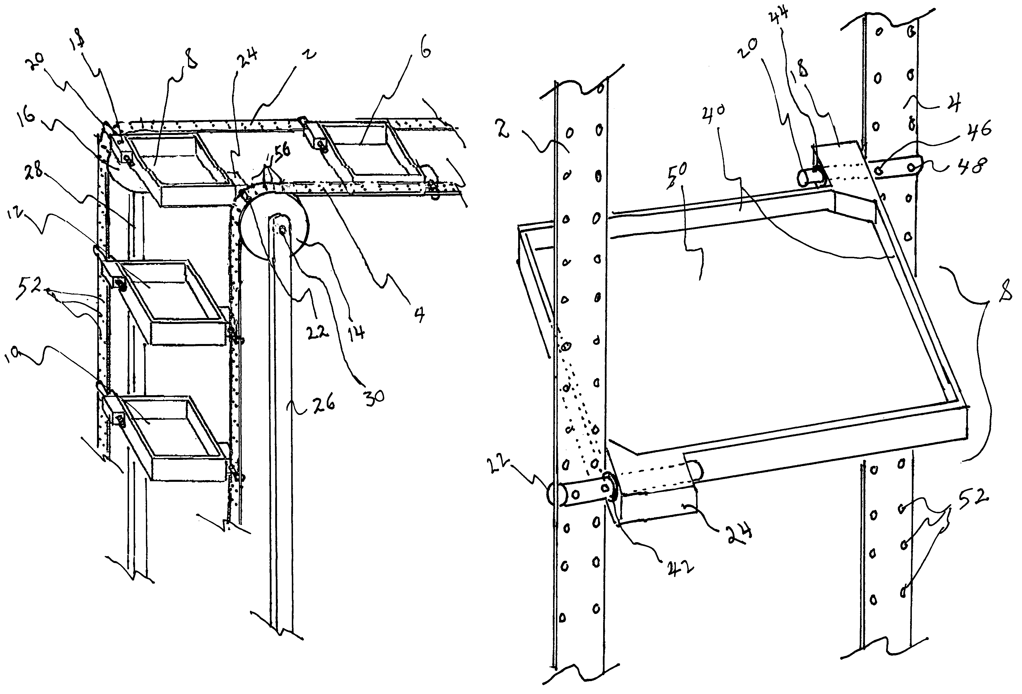
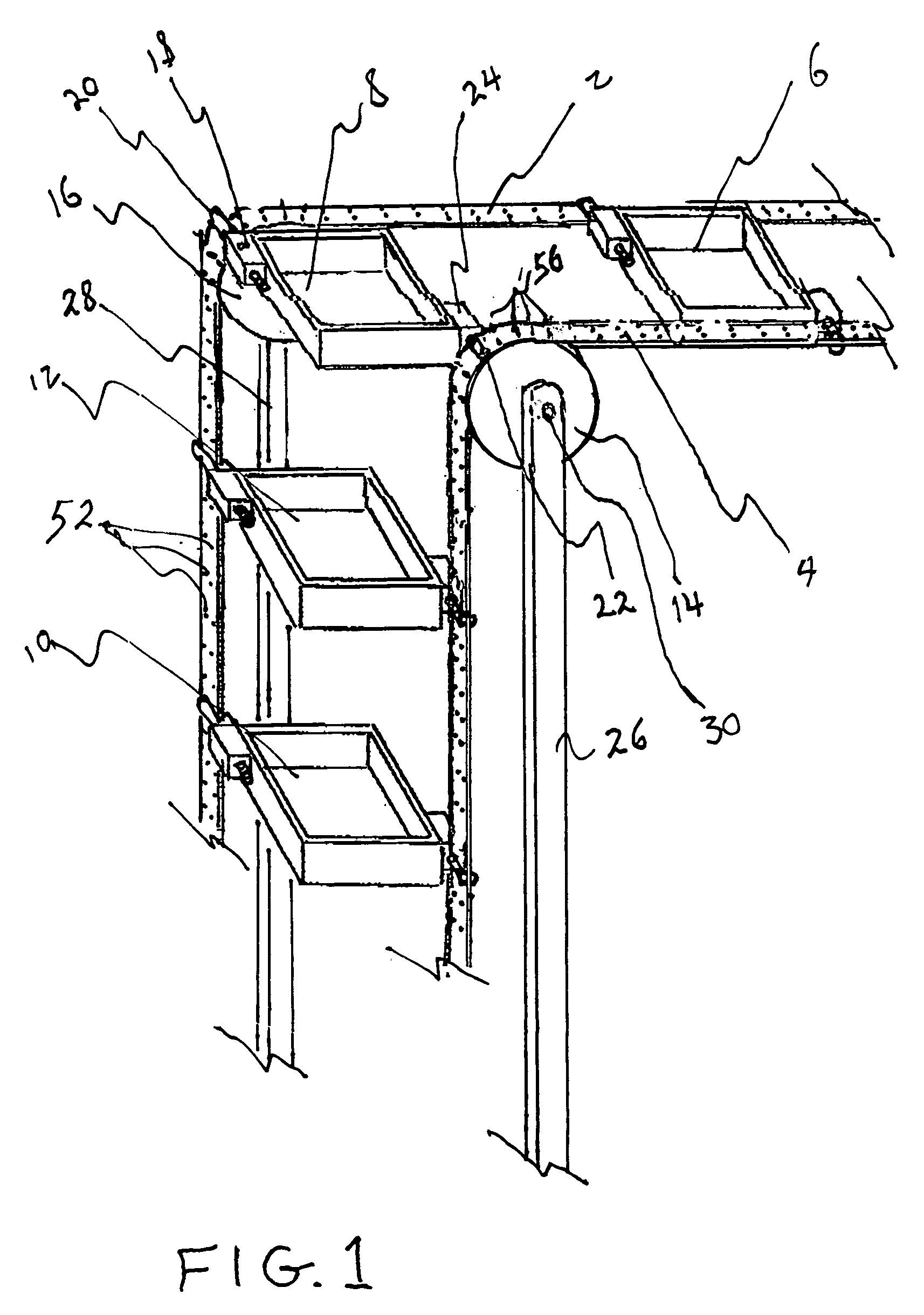
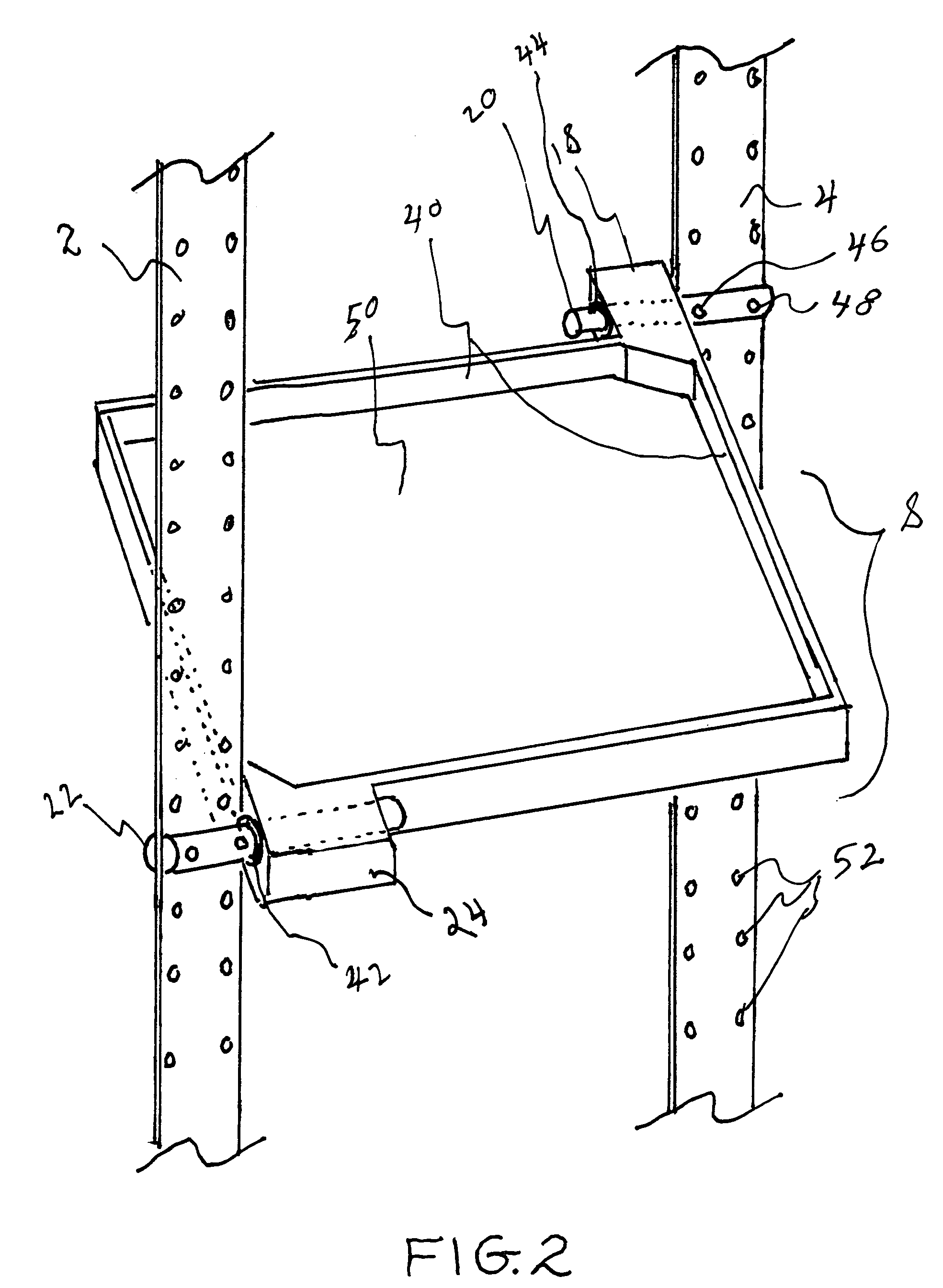
[0013]Referring now to FIG. 1 we see a perspective view of the multi-directional view of the present invention. A pair of stainless steel belts 2, 4 each belt being approximately two inches wide hold a plurality of trays 6, 8, 10, 12. The trays 6, 8, 10, 12 are attached to the belts by pins 20, 22 which can freely rotate within pin holding blocks 18, 24 so that as the belts 2, 4 change orientation as shown in this Figure, the trays can continue to remain in a horizontal orientation. My experiments have shown that a stainless steel be...


PUM


Abstract

Multi-directional conveyor with a pair of conveying belts, a plurality of sprockets, a sprocket holding frame, a gear reduced drive motor and a plurality of four sided trays. The trays are attached to the conveying belts by outwardly facing horizontal pins that are located at opposing offset corners of the trays and are capable of rotating within corner blocks that are affixed to the tray. The pins are fixedly attached to the conveying belts. The conveying belts have a plurality of evenly spaced apertures that accommodate the sprockets so that the drive motor can power the sprockets that are rotatably pinned to the frame thereby causing the belts to be driven in a linear fashion. The belts are capable of changing their angular orientation according to the spatial relationship of one sprocket to another. The belts are made of thin gauge stainless steel.

Description

BACKGROUND OF THE INVENTION[0001]This invention relates generally to the field of conveying devices and more specifically to a multi-directional conveyor.[0002]An Age old problem is how to easily convey objects from one point to another. One well known solution to this problem is the development of conveyor belts. They are traditionally used to transfer items from one location to another. Usually a conveyor belt operates by an endless loop belt of flexible material such as rubber or thin gauge steel or the like which is stretched taught by rollers, one of which is usually driven by a gear reduced motor. In many cases there is a flat support structure that lies under the top layer of belting so that items placed on the belt can be supported as they travel in a linear fashion while riding on the belt. Some conveying belts are segmented so that they can be curved as necessary rather than traveling in a straight line. Some conveyor belts are built to be angled and include anti roll bars...

Claims


Application Information

Patent Timeline
Patent Type & Authority Patents(United States)
IPC IPC(8): B65G17/16B65G17/12B65G47/34
CPCB65G17/123B65G2201/02
Inventor CHAN, EDMUND
Owner CHAN EDMUND
Learn More