Telescoping drilling derrick with guide track and top drive guide assembly

a technology of top drive and derrick, which is applied in the direction of drilling rods, drilling pipes, rotary drilling, etc., can solve the problem that the top drive assembly itself cannot be improved in the operation of the top drive, and the top drive assembly cannot be improved

Inactive Publication Date: 2014-11-25
HORIZONTAL WELL DRILLERS
View PDF22 Cites 15 Cited by
  • Summary
  • Abstract
  • Description
  • Claims
  • Application Information

AI Technical Summary

Benefits of technology

[0015]The present improved top drive assembly focuses on the track and movement aspects of the top drive assembly, but does not address any improvement to the top drive assembly itself with regard to operation of the top drive. The top drive, as used in this improved assembly may be an electric or hydraulic top drive, with the top drive having a body that for purposes of this submission includes the body defining a motor, and possibly a transmission, that is suspended from the derrick or mast of the rig with a great amount of horsepower that turn a shaft to which the drill string is screwed, replacing the traditional Kelly or rotary table, the top drive lessening the manual labor involved in drilling and significantly reducing safety risks to rig workers. Terms typically used to define the other significant components of the top drive beyond the motor would be a short section of pipe called a quill which is connected to the drill string and engaging the motor, a traveling block which suspends the motor from a hook which allows the top drive to be raised and lowered quickly and accurately, and a means to deliver and withdraw drilling fluids and liquids to the bore hole. these features of the top drive will simply be referenced as the top drive body.
[0016]The known advantages of the top drive assembly over alternative drilling engines and means provide an improvement over other drilling rigs including the ability to drill multiple joint stands instead of a single pipe at a time, decrease the incident of stuck pipe and pipe damage, providing a nearly constant rotation of the drilling stand and downhole string, provide a more quick engaging and disengaging pumps or the rotary while removing and restringing pipe, and provide the ability to drill deeper vertical well, to perform directional and horizontal drilling which require a greater torque force than a rotary table rig can deliver, pipe handling features used with top drives using hydraulic arms to move drill pipe and drill collars to and from the pipe racks without worker involvement, the ability to skew into the drill string at any location in the derrick, preferably within the top drive itself, to circulate drilling fluids, continuous rotation when removing the drill string from or tripping back into directional or horizontal wells, and a substantive reduction in drilling costs by reducing the chance of sticking the drill string or losing expensive bottom hole drilling assemblies. There are numerous other advantages associated with the top drive assembly know in the field of art.
[0019]The present improved top drive assembly provides the lateral wheel assembly with a pair of guide tracks forming parallel channels and defining a first channel segment and a second channel segment. Each channel segment further defines an inner surface, a front surface and a rear surface, each surface providing a longitudinal friction reducing pad which may be replaced with wear. Each channel segment is positioned upon a respective top derrick mast guide rail and parallel lower derrick mast guide rail, the guide rails welded to the facing inner surfaces of the front legs of a telescoping derrick mast assembly. Above and below each channel segment are independent upper and lower track wheels which provide a smooth outer surface, each independent upper and lower track wheel being independently adjusted for inner and lateral positioning providing the wheels to be applied outwardly with a force as determined by the operator of the top drive. The wheels also provide and maintain a consistent alignment of the travel pathway of the top drive up and down the rails. Use of the guide tracks having the friction reducing pads and the laterally adjustable track wheels greatly reduces the amount of wear and tear on the lateral wheel assembly and the derrick guide rails, reduces the amount of forces required to raise and lower the top drive assembly and provides for a smoother travel of the top drive assembly up and down the derrick masts.

Problems solved by technology

The present improved top drive assembly focuses on the track and movement aspects of the top drive assembly, but does not address any improvement to the top drive assembly itself with regard to operation of the top drive.

Method used


Image

  • Telescoping drilling derrick with guide track and top drive guide assembly
  • Telescoping drilling derrick with guide track and top drive guide assembly
  • Telescoping drilling derrick with guide track and top drive guide assembly

Examples


Embodiment Construction

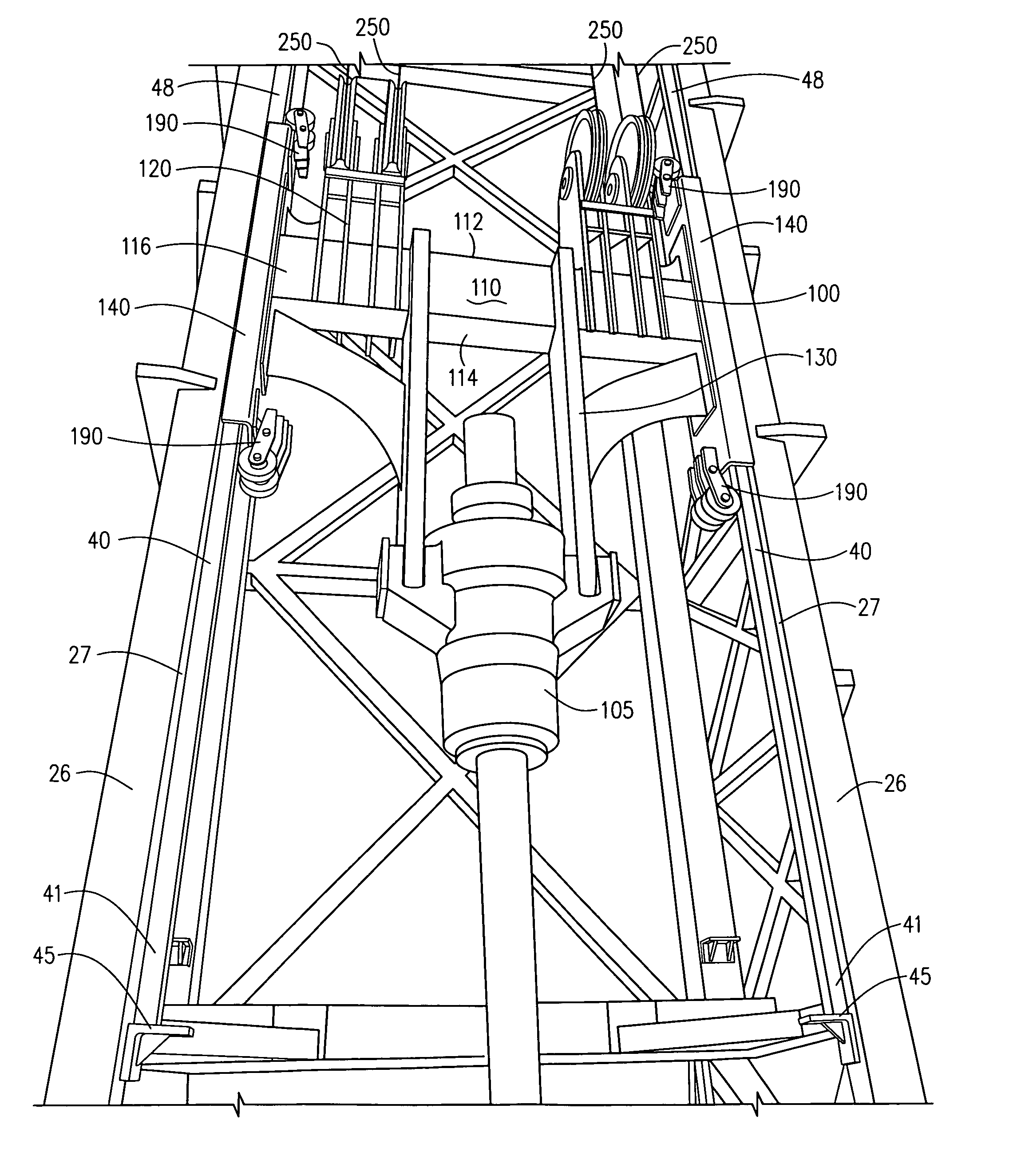
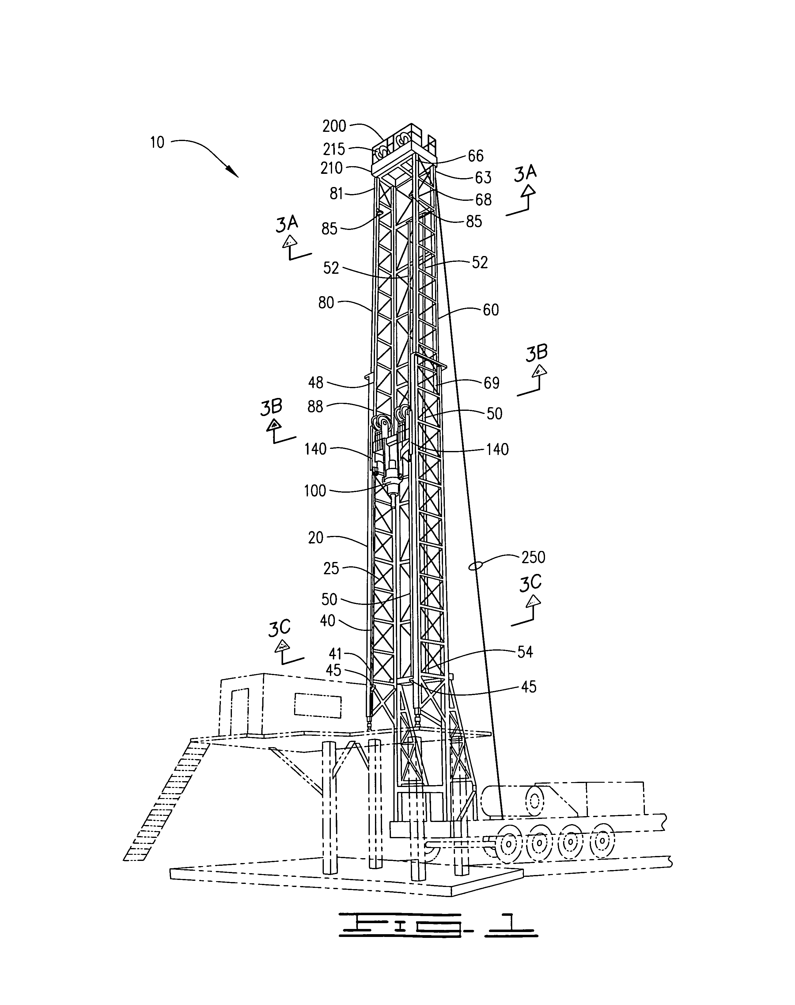
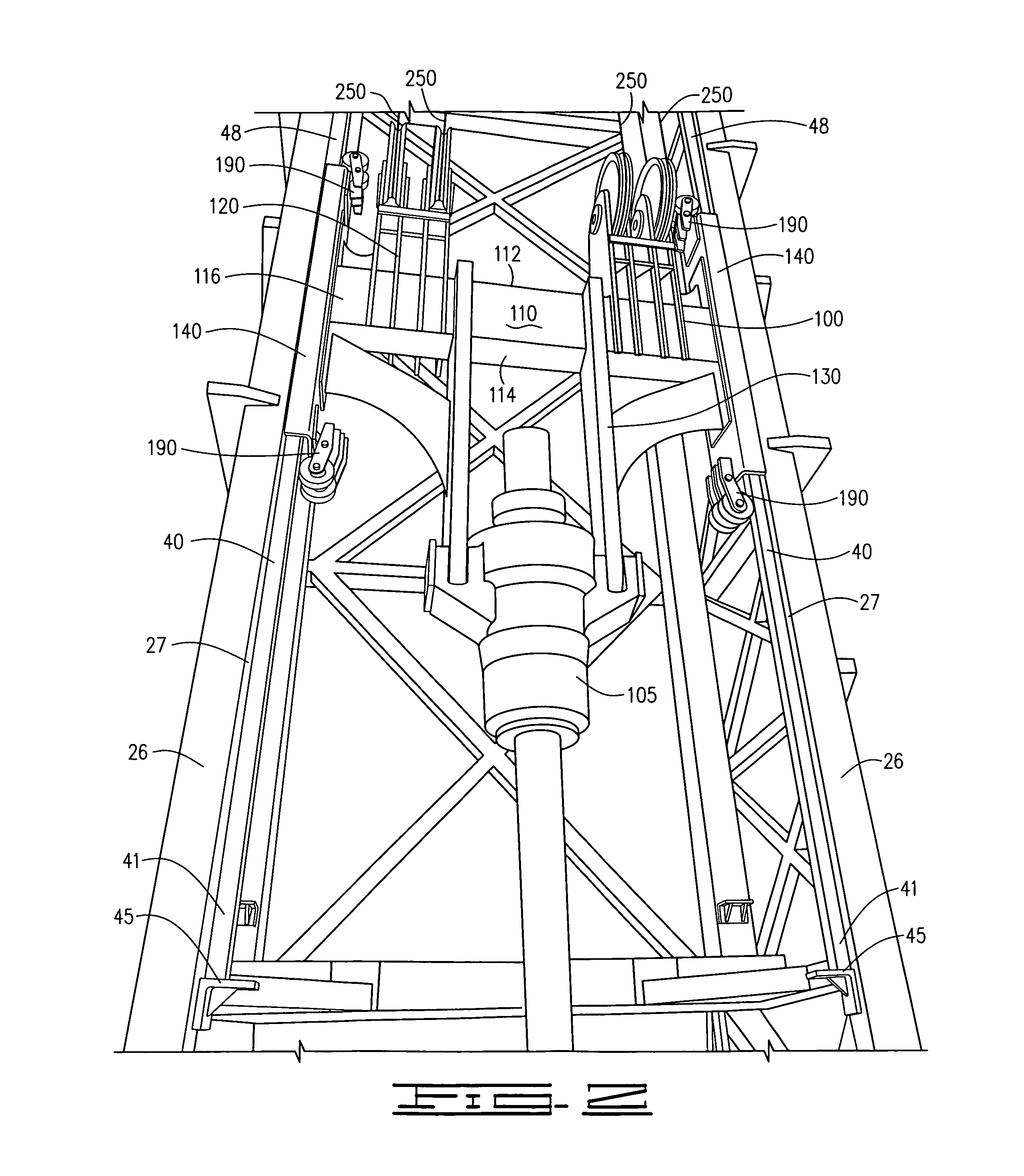
[0035]A telescoping derrick assembly 10 and an improved top drive assembly 100 for use in portable or stationary drilling rigs, as demonstrated in FIGS. 1-8 of the drawings, provides the telescoping derrick assembly 10 having a lower derrick mast 20 defining a pair of parallel rear legs 22 attached by secondary support members 25, each rear leg 22 further attaching a corresponding front leg 26 by secondary support members 25, the front and rear legs forming a rectangular profile with a channel opening 32 between the front legs 26 defining a channel 30, FIG. 3A, an upper derrick mast 60 defining a pair of parallel rear legs 62 attached by secondary support members 64, each rear leg 62 further attaching a corresponding front leg 65 by secondary support members 64, the front and rear legs forming a rectangular profile with a channel opening 72 between the front legs 65 defining a channel 70, FIG. 3C, with the upper derrick mast 60 being slidably engaged within the lower derrick mast 20...


PUM


Abstract

An improved top drive assembly for a telescoping derrick provides the telescoping derrick with two rectangular telescoping section each defining rear legs and front legs defining a longitudinal channel, each set of front legs further defining rails attached to inner facing surfaces upon which lateral guide tracks of the improved top drive assembly are led, each lateral guide tracks providing a set of parallel channel segments having a friction reducing inner lining and an upper and lower track wheel which travel upon the facing surface of each guide rail for smooth and secure travel up and down the derrick during drilling and completion operations.

Description

CROSS REFERENCE TO RELATED APPLICATIONS[0001]Applicant claims the benefit of Provisional Patent Application No. 61 / 461,920, filed on Jan. 25, 2011, filed by the same inventor.I. BACKGROUND OF THE INVENTION[0002]1. Field of Invention[0003]An improved top drive assembly for a telescoping derrick provides the telescoping derrick with two rectangular telescoping section each defining rear legs and front legs defining a longitudinal channel, each set of front legs further defining rails attached to inner facing surfaces upon which lateral guide tracks of the improved top drive assembly are led, each lateral guide tracks providing a set of parallel channel segments having a friction reducing inner lining and an upper and lower track wheel which travel upon the facing surface of each guide rail for smooth and secure travel up and down the derrick during drilling and completion operations.[0004]2. Description of Prior Art[0005]A preliminary review of prior art patents was conducted by the a...

Claims


Application Information

Patent Timeline
Patent Type & Authority Patents(United States)
IPC IPC(8): E21B3/02
CPCE21B19/02E21B3/02E21B17/07E21B19/00E21B3/022
Inventor AKERMAN, STEVE
Owner HORIZONTAL WELL DRILLERS
Why Eureka
Try Eureka