Track adjuster

a technology of track adjuster and track, which is applied in the direction of belt/chain/gearing, mechanical equipment, belt/chain/gearing, etc., can solve the problems of reducing the efficiency associated with the operation of the work machine, slack in the crawler belt, and damage to the crawler belt, so as to prolong the life

Inactive Publication Date: 2005-02-10
KOMATSU LTD
View PDF15 Cites 16 Cited by
  • Summary
  • Abstract
  • Description
  • Claims
  • Application Information

AI Technical Summary

Benefits of technology

[0020] According to the invention, in each of the track adjusters provided for the right and left base carriers, the hydraulic actuator for changing the position of the idler is operated by the control means according to a signal released from the operating condition detecting means, whereby the position of the idler is controlled to adjust tension in the crawler belt so that the tension of the crawler belt can be brought into an optimum condition according to the traveling condition of the vehicle. Accordingly, slack in the crawler belt caused by wear of the crawler belt components such as bushings and pins can be automatically eliminated thereby accomplishing tension optimization.
[0021] The right and left hydraulic actuators are activated and controlled by pressure oil fed from their respective independent hydraulic pumps. A signal generated by the operating condition detecting means for detecting the operating condition of its associated hydraulic actuator is judged by the control means and the position of the idler is changed by making the hydraulic actuator move forward or backward to adjust the tension of the crawler belt. With this arrangement, the crawler belts provided in the right and left base carriers can be respectively brought into an optimum condition according to the traveling condition of the vehicle. Accordingly, the condition of the crawler belts can be optimized, so that their life can be prolonged and the vehicle can travel smoothly.

Problems solved by technology

The crawler belts are constructed by coupling a plurality of track links by pins, and the track links, the coupling components (e.g., bushings and pins), the idlers, the teeth of the drive sprockets begin to wear over a period of time with the result that slack is caused in the wound crawler belts.
If slack occurs in the crawler belts, irregular external force will affect the components of the crawler belts and the power transmission unit, giving damage to the crawler belts.
The track adjuster disclosed in Japanese Patent Kokai Publication No. 7-144668 has, however, revealed the following problems.
In addition, the use of this track adjuster causes a decrease in the efficiency associated with operation of the work machine.
(b) If a crawler belt bites foreign materials such as rocks during vehicle traveling or if earth and sand penetrate into and deposit on the tooth roots of a drive sprocket, causing abnormal tension in the crawler belt, the load on the coil spring increases, imposing a heavy load on every parts of the track frame.
In view of this, the work machine needs a sturdy structure, which leads to an increase in vehicle weight and therefore additional cost.
To withstand the impulsive load occurring at that time, the components of the crawler belts are required to have sufficient strength, which leads to an increase in the weight of the components.
As a result, additional cost becomes inevitable.
Such a control system is seemingly rational, however, imposes the following problem: Since work machines such as bulldozers are usually operated on the unleveled ground and therefore contaminated with earth and sand at their crawler travel units, the light beam of the sensor is likely to be cut off by earth and sand during operation.
Therefore, such a sensor lacks accuracy.
Even when a bobbin-shaped scale is used in addition to the laser as a means for measuring distance, if earth and sand penetrate into its measuring part during measurement (operation), the measuring function will be hampered, resulting in a failure in accomplishment of intended aims.

Method used


Image

  • Track adjuster
  • Track adjuster
  • Track adjuster

Examples


Embodiment Construction

[0032] Referring now to the accompanying drawings, a track adjuster will be concretely described according to preferred embodiments of the invention.

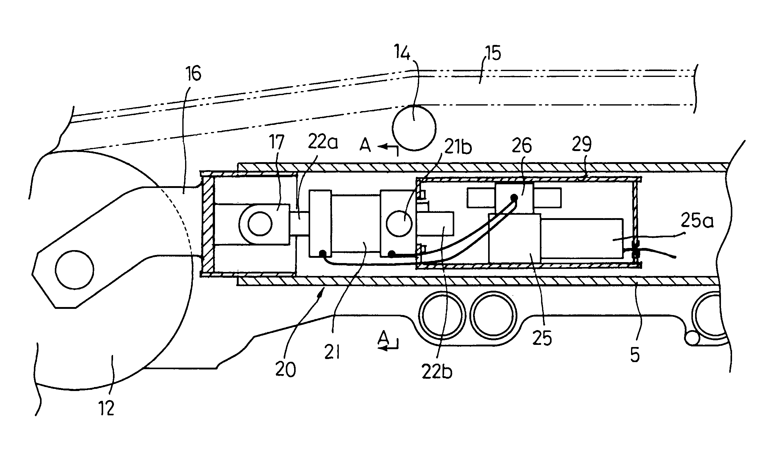
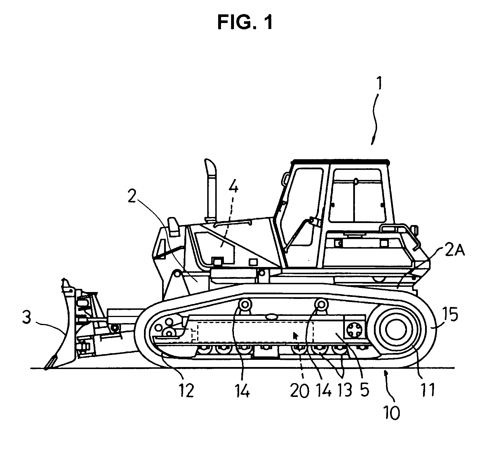
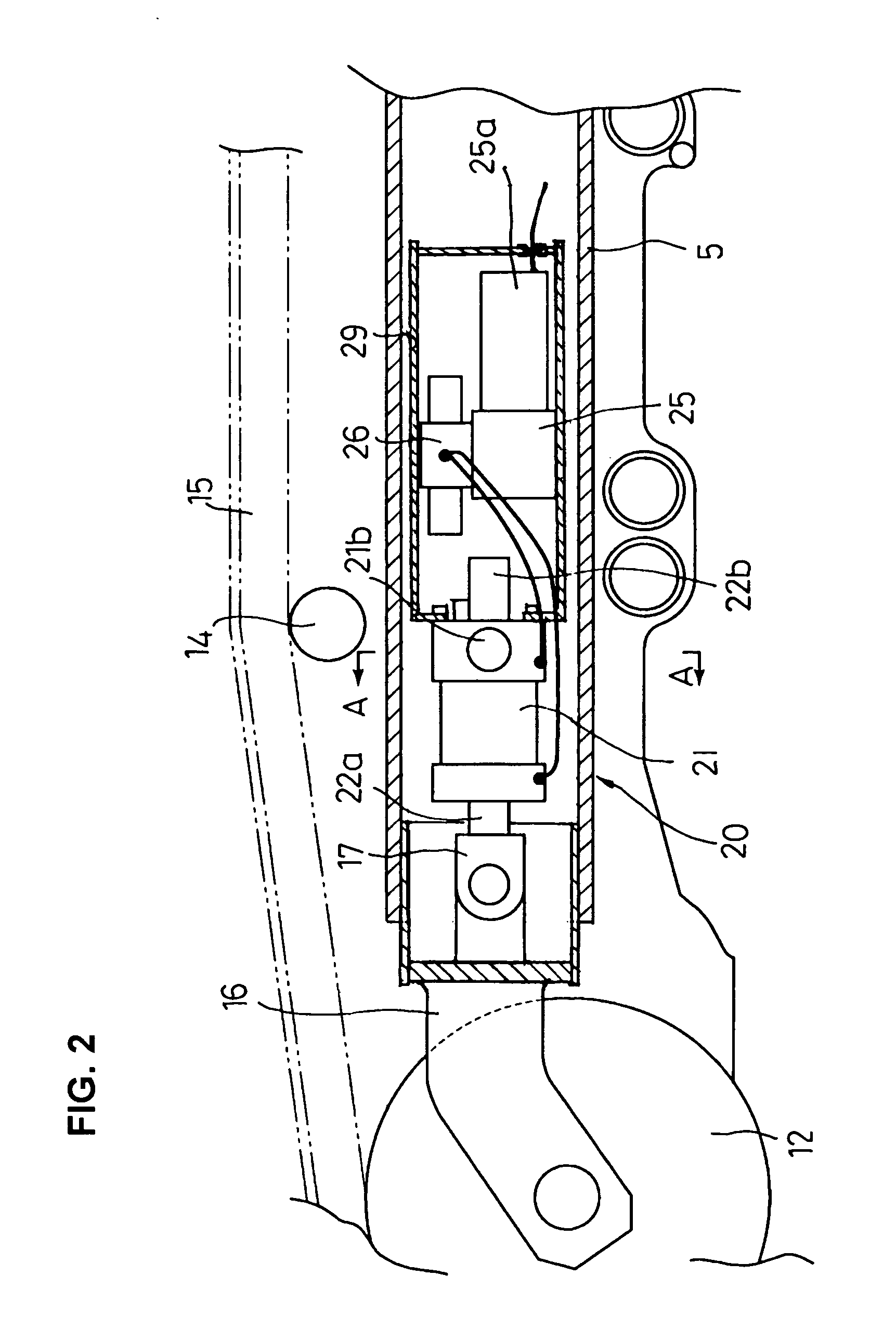
[0033]FIG. 1 is a side view of a work machine equipped with track adjusters constructed according to a first embodiment of the invention. FIG. 2 is a longitudinal sectional view of the track adjuster of the first embodiment. FIG. 3 diagrammatically shows the track adjuster of the first embodiment and its control unit.

[0034] The first embodiment is associated with a track adjuster which is applied to a bulldozer 1 shown in FIG. 1, the bulldozer 1 serving as a track-type work machine for use in operations such as earth moving and ripping. The bulldozer 1 includes work implements such as a blade 3 and a ripper (not shown) which are operated by a hydraulic drive. In the bulldozer 1, an engine 4 is mounted on a vehicle body 2, for activating the blade 3 and the ripper and making the vehicle move. This bulldozer 1 has a crawler travel unit ...


PUM


Abstract

Right and left track adjusters each comprise a tension adjusting cylinder operable in forward and backward directions in the same condition; a motor-driven hydraulic pump; and a direction selector valve disposed in a hydraulic circuit for connecting the motor-driven hydraulic pump to the tension adjusting cylinder. The hydraulic circuit includes operating condition detecting means for detecting the operating condition of the tension adjusting cylinder. A controller located in the work vehicle judges a signal released from the operating condition detecting means. If the pressure condition is determined to be higher than a preset value, the tension adjusting cylinder is moved backward to avoid abnormal tension in the crawler belt. If it has a steady-state value, the movement of the tension adjusting cylinder is controlled according to a judgment based on a set value corresponding to the traveling direction of the vehicle, thereby properly adjusting the tension of the crawler belt.

Description

TECHNICAL FIELD [0001] The present invention relates to a track adjuster for automatically adjusting the tension of a crawler belt of a track-type work machine such as a bulldozer during traveling. BACKGROUND ART [0002] A known track-type work machine has crawler belts each of which is wrapped around its corresponding drive sprocket and idler. The drive sprocket is supported by a track frame as a base carrier and rotatively driven by a power from a drive source, and the idler is supported on the track frame so as to be movable in forward and backward directions. The crawler belts are each guidingly supported by track rollers at the ground engaging side and by track carrier rollers at the ground unengaging side. For creating and maintaining tension in the crawler belts, a track tensioner of the coil spring type or hydraulic cylinder type is interposed between each yoke for supporting a bearing for the idler and the track frame. [0003] The crawler belts are constructed by coupling a p...

Claims


Application Information

Patent Timeline
Patent Type & Authority Applications(United States)
IPC IPC(8): B62D55/30F16H7/08
CPCF16H2007/0812B62D55/305
Inventor TAMARU, MASATAKEYAMAMOTO, TEIJIYAMAMOTO, SHIGERU
Owner KOMATSU LTD
Why Eureka
Try Eureka