Photomask, method for producing the same, and method for forming pattern using the photomask

Inactive Publication Date: 2006-06-13
PANASONIC CORP
View PDF14 Cites 13 Cited by
  • Summary
  • Abstract
  • Description
  • Claims
  • Application Information

AI Technical Summary

Benefits of technology

[0023]With the foregoing in mind, an object of the present invention is to provide a photomask which makes it possible to form a small pattern under the same exposure

Problems solved by technology

However, the pattern forming method of the first conventional example has had the following problems.
As a result, costs for masks are increased and also the number of process steps in a lithograph process is increased to cause reduction in throughput or increase in production costs.
Thus, light-shielding properties of a T-shaped light-shielding pattern, for example, can not be improved.
Therefore, a pattern layout with which effects of the phase shifter can be utilized is limited.
Moreover, the pattern forming method of the second conventional example has had the following problems.
(3) Depending on a half-tone phase-shifting mask, it is difficult to simultaneously form an isolated contact pattern in which contacts are arranged so as to be isolated from each other and a densely arranged contact pattern in which contacts are densely arranged by exposure using the same light source and with sufficient finishing quality. In the same manner, it is difficult to simultaneously form an isolated line pattern in which lines are arranged so as to be isolated from each other and a densely arranged line pattern in which lines are densely arranged by exposure using the same light source and with sufficient finishing quality. More specifically, assume that the isolated contact pattern is formed. If vertical incident exposure is performed with the same small light source having a low coherence degree of about 0.5 or less (see FIG. 30(a)) and being used for illumination by only vertical incident components that enter vertically to a mask, an improved contrast and increased depth of focus can be achieved. However, if vertical incident exposure is used to form the densely arranged contact pattern, the contrast and the depth of focus are significantly deteriorated. On the other hand, assume that the densely arranged contact pattern is formed. If off-axis illumination (oblique

Method used


Image

  • Photomask, method for producing the same, and method for forming pattern using the photomask
  • Photomask, method for producing the same, and method for forming pattern using the photomask
  • Photomask, method for producing the same, and method for forming pattern using the photomask

Examples


first embodiment

[0107]First, a method for improving resolution with a photomask invented by the inventor of the present application to achieve the present invention, and, more specifically, an “outline enhancement method” to improve the resolution of an isolated space pattern will be described.

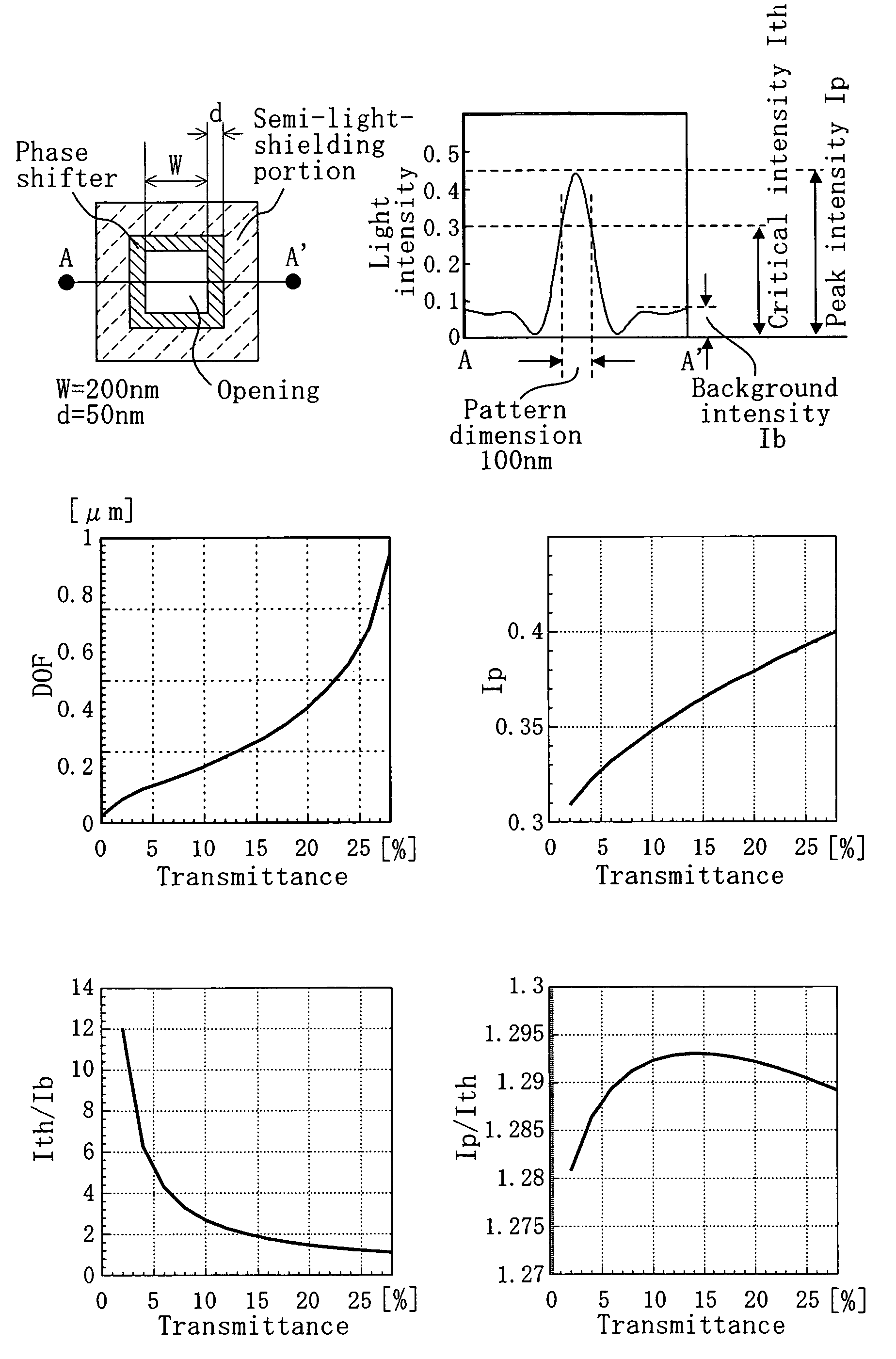
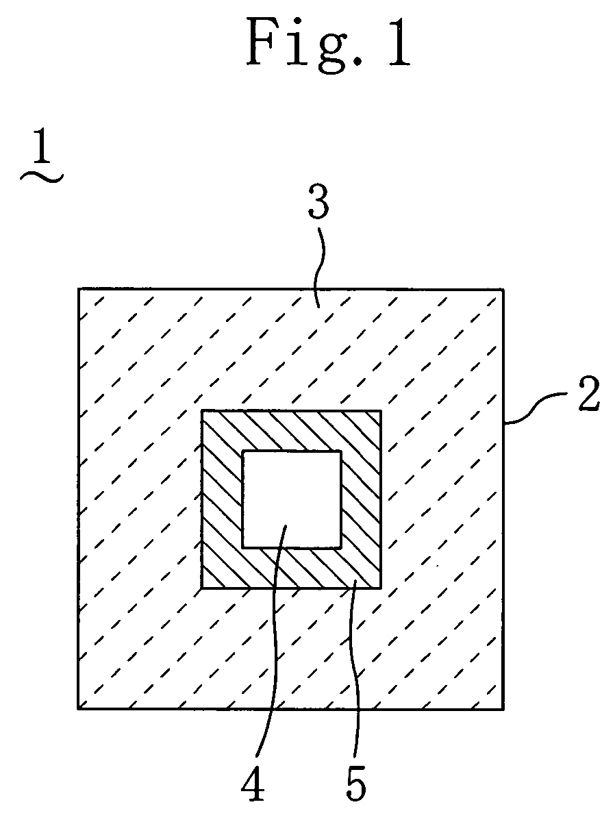
[0108]FIG. 1 is a plan view of a photomask using an outline enhancement method in accordance with a first embodiment of the present invention (hereinafter, referred to as an “outline enhancement mask”). More specifically, FIG. 1 shows a plan view of an outline enhancement mask in which a light-transmitting portion corresponding to an isolated contact pattern is provided.

[0109]As shown in FIG. 1, an outline enhancement mask 1 includes a transparent substrate 2 having light-transmitting properties with respect to exposure light, a semi-light-shielding portion 3 formed on the principal surface of the transparent substrate 2 and having a transmittance which allows exposure light to be partially transmitted, a lig...

second embodiment

[0175]Next, a photomask using a method for improving resolution with a photomask invented by the inventor of the present application to achieve the present invention, and, more specifically, a photomask using a “center line enhancement method” to improve the resolution of isolated line patterns will be described.

[0176]FIG. 12 is a plan view of a photomask using a center line enhancement method in accordance with a second embodiment of the present invention (hereinafter, referred to as “image enhancement mask”). More specifically, FIG. 12 is a plan view of an image enhancement mask for forming an isolated line pattern.

[0177]As shown in FIG. 12, an image enhancement mask 6 includes a transparent substrate 7 having light-transmitting properties with respect to exposure light, a semi-light-shielding portion 8 formed on the transparent substrate 7, having a transmittance which allows part of exposure light to be transmitted and corresponding to an isolated line pattern, and a phase shift...

third embodiment

[0190]Hereinafter, a photomask in accordance with a third embodiment of the present invention and a method for generating mask data for the photomask will be described with reference to the accompanying drawings.

[0191]FIG. 17 shows a flow chart of a mask data generation method in accordance with the third embodiment, using the outline enhancement method and the center line enhancement method. More specifically, FIG. 17 is a flowchart of a mask data generation method in which a mask pattern is formed based on a desired pattern which is to be formed using a photomask. Also, FIGS. 18(a) through 18(d) and FIGS. 19(a) and 19(d) are plan views illustrating respective process steps for forming a mask pattern for space pattern formation by using the mask data generation method of FIG. 17. Moreover, FIGS. 20(a) through 20(d) and FIGS. 21(a) through 21(c) are plan views illustrating respective process steps for forming a mask pattern for line pattern formation by using the mask data generatio...


PUM


Abstract

A mask pattern to be provided on a transparent substrate 2 includes a semi-light-shielding portion 3 which transmits exposure light in the same phase as that of the light-transmitting portion 4 and a phase shifter 5 which transmits exposure light in a phase opposite to that of the light-transmitting portion 4. The semi-light-shielding portion 3 has a transmittance which allows exposure light to be partially transmitted. The phase shifter 5 is provided in a region of the mask pattern in which light transmitted through the phase shifter 5 can cancel part of the light transmitted through the light-transmitting portion 4 and the semi-light-transmitting portion 3.

Description

TECHNICAL FIELD[0001]The present invention relates to a photomask for forming a small pattern used for producing a semiconductor integrated circuit device, a method for producing the photomask and a method for forming a pattern using the photomask.BACKGROUND ART[0002]In recent years, it is increasingly necessary to reduce the size of circuit patterns for high integration of a large-scale integrated circuit device (hereinafter, referred to as “LSI”) that can be achieved with semiconductors. As a result, reduction of the width of a line for wiring patterns constituting a circuit or reduction of the size of contact hole patterns (hereinafter, referred to as “contact patterns”) that connect between layered wirings formed with an insulating layer therebetween have become very important.[0003]Hereinafter, reduction of the size of wiring patterns and contact patterns with a conventional light-exposure system will be described by using a positive resist process as an example. In a positive ...

Claims


Application Information

Patent Timeline
IPC IPC(8): G01F9/00G03F1/29G03F1/32G03F1/36G03F1/68
CPCG03F1/144G03F1/32G03F1/30G03F1/29G03F1/36
Inventor MISAKA, AKIO
Owner PANASONIC CORP
Why Eureka
Try Eureka