System for highly linear phase modulation

Active Publication Date: 2006-06-13
QUINTIC MICROELECTRONICS WUXI
View PDF1 Cites 7 Cited by
  • Summary
  • Abstract
  • Description
  • Claims
  • Application Information

AI Technical Summary

Benefits of technology

[0007]In one embodiment, apparatus is provided for linear phase modulation utilizing a phase-locked loop (PLL). The apparatus includes a PLL utilizing fractional N synthesis to realize a non-integer divide value. A two-port voltage-controlled oscillator includes a first port controlled by the phase-locked loop and a second port accessed for direct modulation. A second input to the fractional-N phase-locked loop is provided to remove the modulation introduced at the second port. Lastly, a calibration loop is provided wherein a frequency offset applied at the second port is adjusted until it cancels the effects of a known frequency offset introduced to the fractional-N phase-locked loop.
[0008]In one embodiment, apparatus is provided for linear phase modulation utilizing a phase-locked loop. The apparatus comprises a phase-locked loop (PLL), utilizing fractional N synthesis, where an N counter in a feedback loop is pseudo-randomly switched between integer values to realize a non-integer divide value. The apparatus also comprises a two-port voltage-controlled oscillator, the first port controlled by the phase-locked loop and a second port accessed for direct modulation. In one embodiment, the second port utilizes MOSFET capacitors that present an effective capacitance to the voltage-controlled oscillator equal to the time-averaged value of two capacitances, the value linearly changing with the applied control voltage. A second input to the fractional-N phase-locked loop is provided to remove the phase modulation introduced at the voltage-controlled oscillator. Lastly, a calibration loop is provided wherein a frequency offset applied at the voltage-controlled oscillator's second port is adjusted until it cancels the effects of a known frequency offset introduced to the fractional-N phase-locked loop.
[0009]In another embodiment included in the present invention, apparatus is provided for calibration of a phase-locked loop used for phase modulation. The apparatus comprises a sampling circuit that stores the control voltage of the phase-locked loop. The control voltage indicates the nominal operating point of the loop. A window comparator is provided that compares the sampled control voltage and nominal operating point of the loop to the present control voltage

Problems solved by technology

However, the typical I/Q modulator requires several powe

Method used


Image

  • System for highly linear phase modulation
  • System for highly linear phase modulation
  • System for highly linear phase modulation

Examples


Example

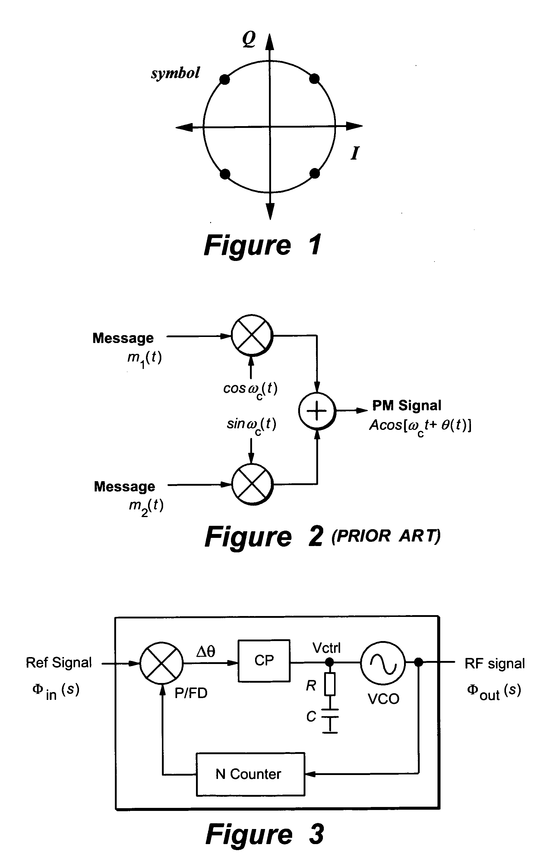
[0034]FIG. 3 shows a phase-locked loop (PLL) that is used to synthesize a radio frequency carrier signal. The PLL forms a feedback system that consists of a voltage-controlled oscillator (VCO), N counter, phase / frequency detector (P / FD), charge pump (CP) and RC integration filter.

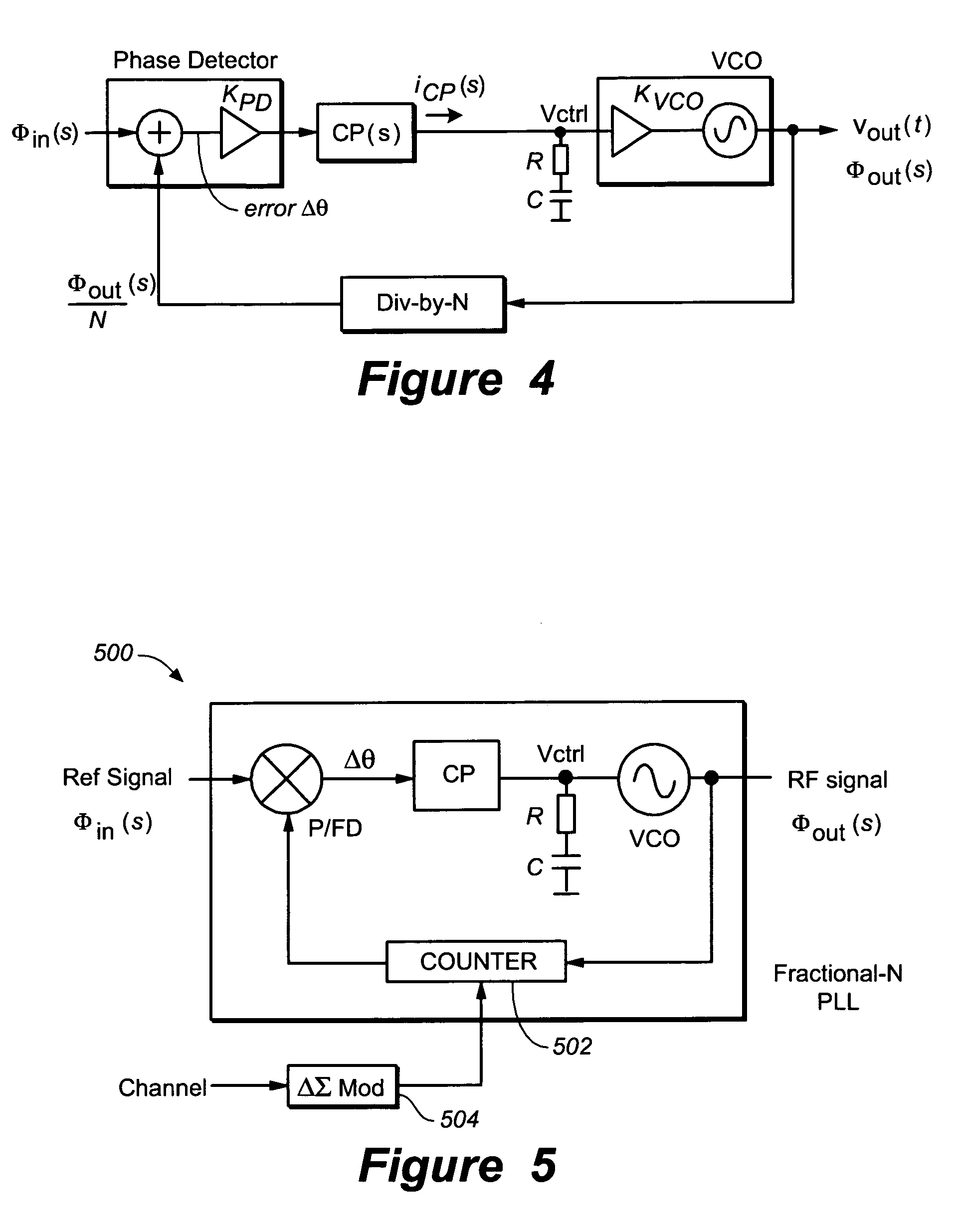
[0035]FIG. 4 shows a mathematical model of the PLL shown in FIG. 3. The VCO produces an output signal at a frequency set by control voltage vctrl that can be expressed as;

vout(t)=Ac cos(ωfreet+Kvco∫vctrl(t)dt)

where ωfree is the free-running frequency of the VCO and Kvco is its gain function. The gain function Kvco describes the relationship between the excess phase of the carrier Φout(s) and the control voltage vctrl, i.e.;

[0036]Φout⁢⁢(s)vctrl⁢⁢(s)=Kvcos

The N counter simply divides the output phase Φout(s) by N. When the PLL is locked, the phase detector (P / FD) and CP combination generate an output signal iCP(s) that is proportional to the phase difference Δθ between two periodic signals that are input to t...


PUM


Abstract

System for highly linear phase modulation. Apparatus is provided for linear phase modulation utilizing a phase-locked loop (PLL). The apparatus includes a PLL utilizing fractional N synthesis to realize a non-integer divide value. A two-port voltage-controlled oscillator includes a first port controlled by the phase-locked loop and a second port accessed for direct modulation. A second input to the fractional-N phase-locked loop is provided to remove the modulation introduced at the second port. Lastly, a calibration loop is provided wherein a frequency offset applied at the second port is adjusted until it cancels the effects of a known frequency offset introduced to the fractional-N phase-locked loop.

Description

CROSS REFERENCE TO RELATED APPLICATIONS[0001]This Application is a Continuation of U.S. patent application Ser. No. 10 / 420,952 filed on Apr. 21, 2003, now U.S. Pat. No. 6,774,740. The application Ser. No. 10 / 420,952 claims the benefit of priority from a U.S. Provisional Patent Application entitled “HIGHLY LINEAR PHASE MODULATION” Ser. No. 60 / 374,040 filed on Apr. 19, 2002, the disclosure of which is incorporated by reference herein in its entirety for all purposes.FIELD OF THE INVENTION[0002]The present invention relates generally to phase modulators, and more particularly, to a highly linear architecture for direct phase modulation of a phase-locked loop.BACKGROUND OF THE INVENTION[0003]Phase modulation schemes—techniques that convey information using the phase of the carrier signal—are effective communication methods. A popular phase modulation scheme is quaternary phase shift keying (QPSK).[0004]FIG. 1 shows a constellation diagram that illustrates how QPSK maps two-bit digital d...

Claims


Application Information

Patent Timeline
IPC IPC(8): H03C3/00H04L27/20H03C3/09
CPCH03C3/0925H03C3/0933H04L27/2042H03C3/0958H03C3/0941
Inventor GROE, JOHN
Owner QUINTIC MICROELECTRONICS WUXI
Why Eureka
Try Eureka