Intelligent locator system

a technology of intelligent locators and locators, applied in the field of intelligent locators, can solve the problems of requiring an active response, only allowing locating equipment in the network, and broadcasting an announcement throughout the entire facility is distracting to all, and achieves the effect of preventing synchronization

Inactive Publication Date: 2006-06-13
DWYER PRECISION PRODS
View PDF29 Cites 29 Cited by
  • Summary
  • Abstract
  • Description
  • Claims
  • Application Information

AI Technical Summary

Benefits of technology

[0008]According to the present invention there is provided a locating and monitoring system installable on the premises of a facility, the system including at least one transmitter means adapted for movement about the facility with a person, with an animal or with equipment to allow identification of such transmitter means at any of diverse sites in the facility,

Problems solved by technology

Such a network does not allow for locating equipment, only personnel.
Also, broadcasting an announcement throughout the entire facility is distracting to all and requires an active response by the person being located.
Furthermore, it is impractical with such network to maintain an up-to-date register for monitoring the location of personnel.
U.S. Pat. Nos. 3,436,320; 3,696,384; and 3,739,329 disclose utilizing ultrasonic transmitters and receivers; however, there are disadvantages because the use of ultrasonics in these systems causes excess battery drain in the transmitters; and the ultrasonic signals pass through walls in a facility resulting in erroneous location indications.
Additionally, the infrared emitters operate continuously which degrades battery longevity.
However, the receiver can only detect the transmitted code word over a limited range, and only when the receiver is positioned so as to be in the “line of sight” of the transmitter.
As a result, this prior art system also suffers from several inherent disadvantages.
First, because a receiver only detect

Method used


Image

  • Intelligent locator system
  • Intelligent locator system
  • Intelligent locator system

Examples


Embodiment Construction

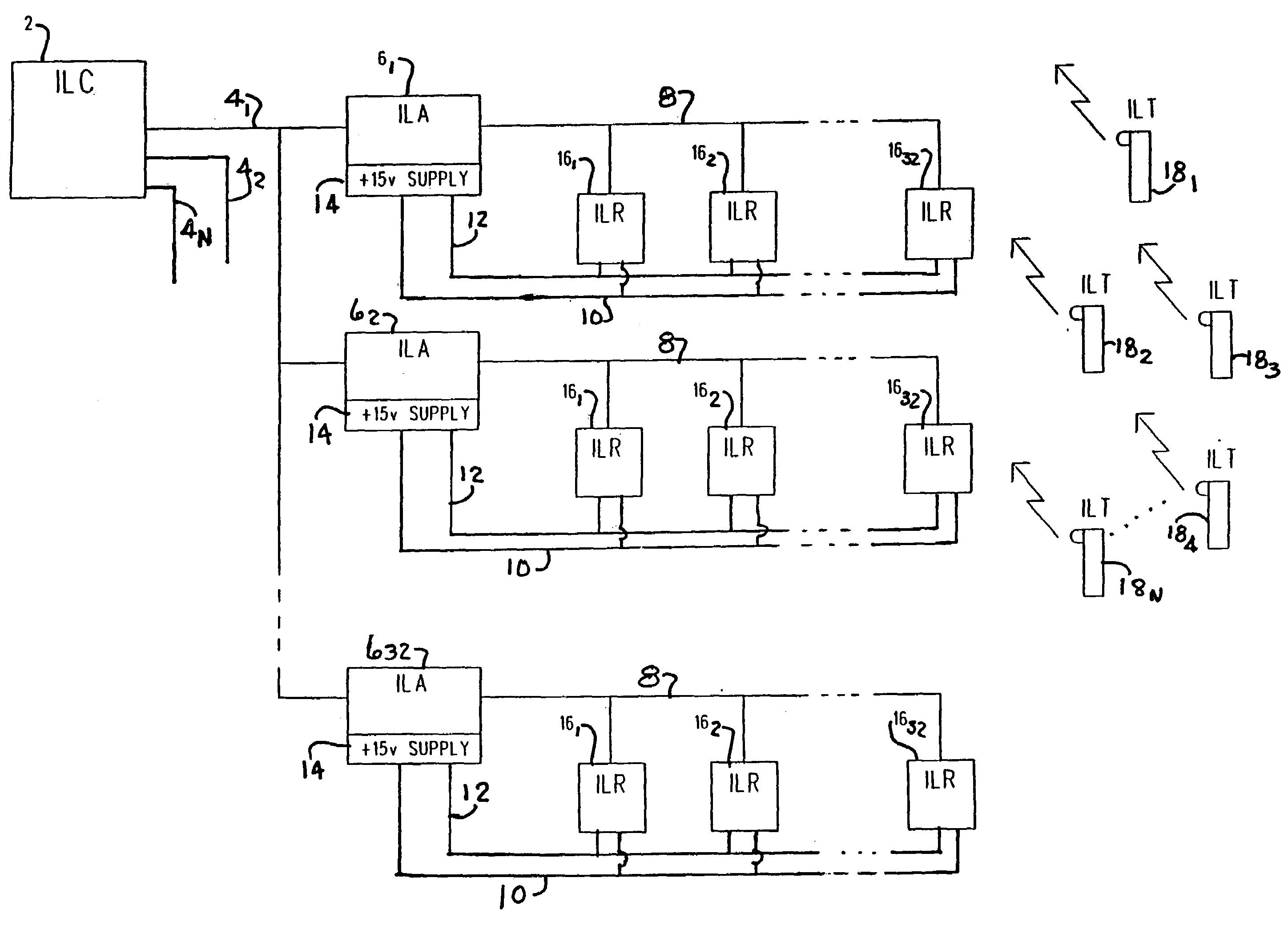
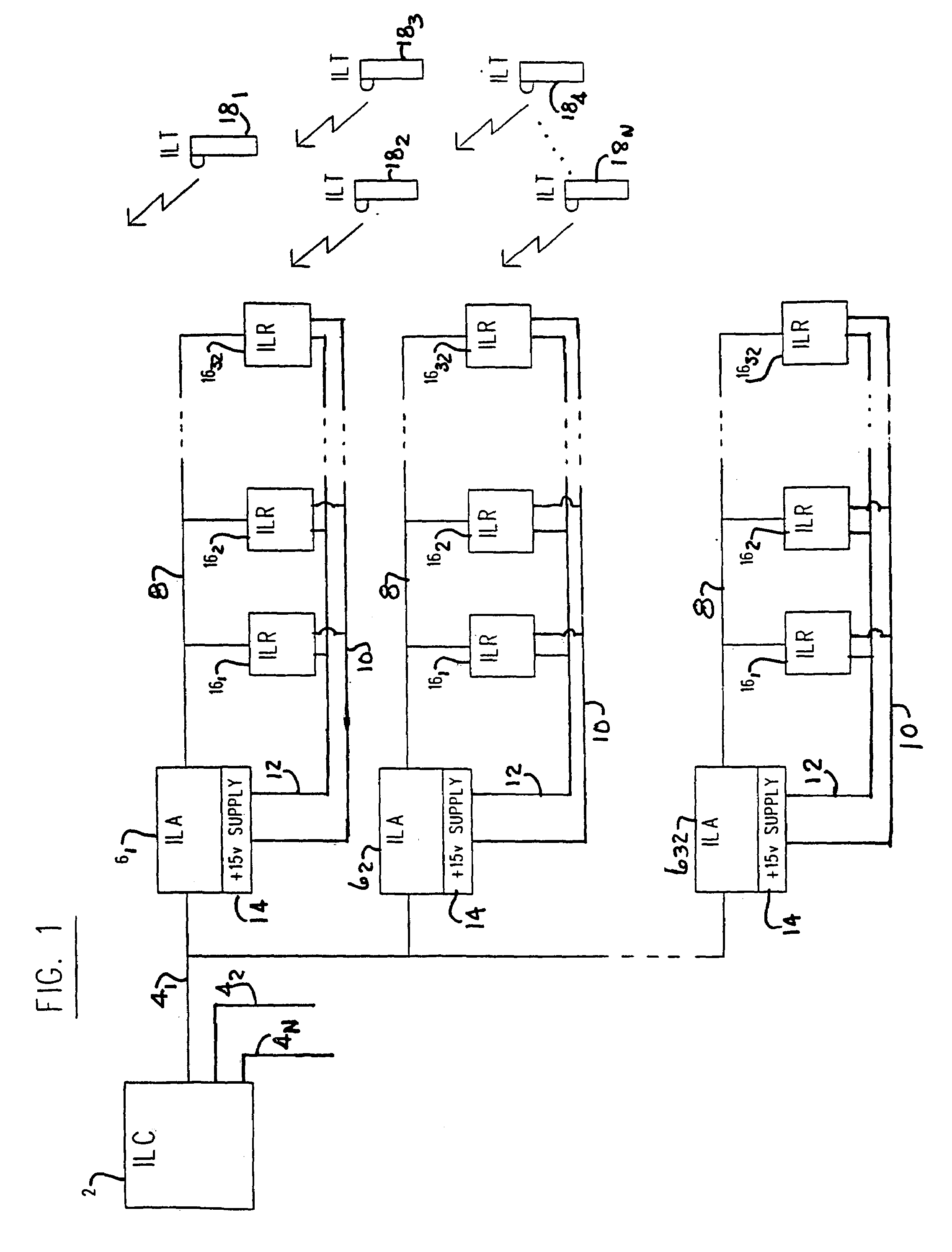
[0027]Referring first now to the block diagram of FIG. 1, there is illustrated one form of intelligent locator system according to the present invention which is useful as a stand alone system for tracking and locating persons and equipment in a hospital; tracking and locating persons and / or product and equipment in a factory, warehouse, retail store or other space; keep records of progress of new product through the production process in a factory, and tracking animals in a storage and feeding facility.

[0028]The intelligent locator system of FIG. 1 includes a central control computer such as a Personal Computer having a 386 central processor identified for the purpose of disclosure of the present invention as an intelligent locator computer 2 because of interfacing with allied components of the system. A serial data bus 4 supplies commands between a serial port of the computer 2 at least one and up to preferably 32 local gathering stations identified as intelligent locator arbitrat...


PUM


Abstract

A locating and monitoring system includes transmitters worn by a person, animal, or equipment to transmit an unique identification code while moving about a facility. The code is transmitted by pulse bursts at diverse times during predetermined time intervals to prevent synchronization with resident signals in the facility. Receivers in the walls or ceilings of the facility respond to the infrared radiation of the pulse bursts and validate the identification code by a checksum of the code through a comparison with a checksum transmitted with the code. The receivers deliver validated codes to arbitrators and receive back signals indicative of the level of an individual assigned to a class wearing the transmitters. Signals from the receivers are received by arbitrators which forward the codes to a CPU for recording start and stop events indicative of movement by transmitters into and out of the reception range of the various receivers.

Description

[0001]This application is a continuation of application Ser. No. 07 / 957,662, filed Oct. 7, 1992 now U.S. Pat. No. 5,426,425.BACKGROUND OF THE INVENTION[0002]1. Field of the Invention[0003]The present invention relates generally to an electronic locating and annunciating system for a facility and, more particularly, to a system which can continuously operate to maintain a registry of the locations in the facility of individuals and equipment; and store and generate reports of a real time record of movement from location to location of individuals and equipment in the facility.[0004]2. Description of the Prior Art[0005]The need to maintain an up-to-date registry of the location of the personnel and equipment in a facility such as a building is oftentimes required to allow efficient operation. While the present invention is not so limited, an intelligent locator system is needed in a hospital setting, for example, to quickly locate operating personnel or emergency equipment at critical...

Claims


Application Information

Patent Timeline
IPC IPC(8): G08B5/22G07C9/00G08B3/10
CPCG08B3/1083G07C9/00111G07C9/28
Inventor CONRAD, ALEXANDERBELL, CHARLES
Owner DWYER PRECISION PRODS
Why Eureka
Try Eureka