
Circuitry for linear control of head flying height using thermal means

a technology of linear control and flying height, applied in the direction of maintaining head carrier alignment, recording information storage, instruments, etc., can solve the problems of increasing difficulty in improving heat sinking, increasing power dissipation in write elements, etc., and achieve the effect of reducing high frequency disturban

Inactive Publication Date: 2006-06-13
WESTERN DIGITAL TECH INC
View PDF5 Cites 28 Cited by
  • Summary
  • Abstract
  • Description
  • Claims
  • Application Information

AI Technical Summary

Benefits of technology

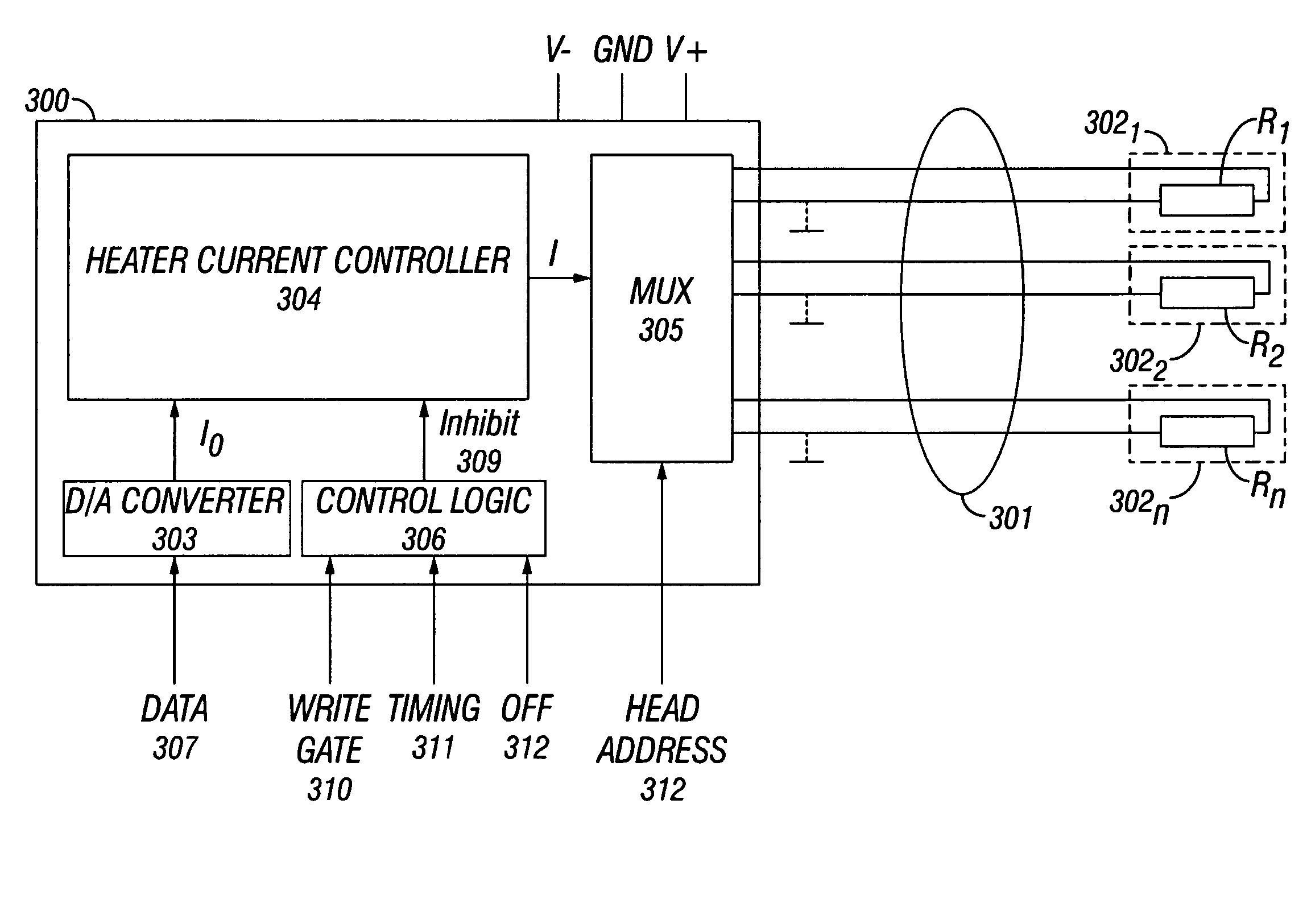
The present invention provides a technique for controlling pole-tip protrusion in a hard disk drive by controlling the spacing between the pole tips of a write element and the magnetic medium in a linear manner using a control signal. This is achieved by a slider flying-height controller that includes a heater current controller and a multiplexer. The heater current controller receives an input signal and outputs a heater control current that causes a spacing decrease between the pole tips of the write element and the magnetic medium that is proportional to the input signal. The heater current controller can include a square-root circuit or a current-to-voltage converter to generate the control current. The invention also includes a common voltage level generator that has an output with a potential that is different from ground and can complete a current path for the control current through the heating element. The common voltage level can be selected to maximize the voltage headroom for the heating element.

Problems solved by technology

Improving the heat sinking, however, becomes increasingly difficult as the dimensions of the write element decrease and as the data rate increases.
As the data rate increases and write current reversal times decrease, the power dissipation in the write element goes up due the increased eddy current losses in the yoke.

Method used


Image

  • Circuitry for linear control of head flying height using thermal means
  • Circuitry for linear control of head flying height using thermal means
  • Circuitry for linear control of head flying height using thermal means

Examples


Embodiment Construction

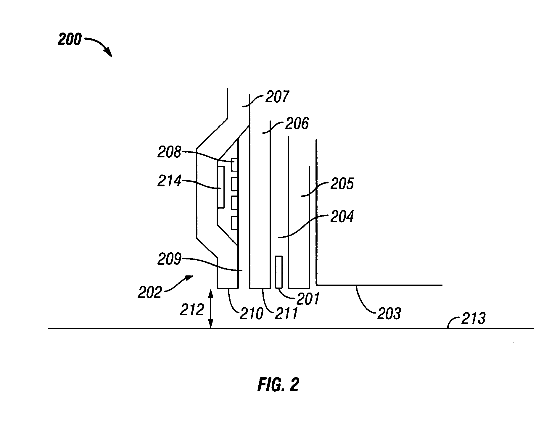
[0026]The present invention provides the ability to control pole-tip protrusion of a write element using a control signal by keeping the write element at a constant temperature during both read and write operations so that the clearance between the pole tips and the magnetic media (i.e., the flying height of the slider) can be controlled in a linear manner for, for example, improved reading performance during a read-retry or during a cold drive start. When the drive is in a read operation (i.e., not writing), a heating element that is positioned in close proximity to a write element that is on the same slider body that has been selected for the read operation is used to keep the write element at the same temperature as when the drive is in a write operation. The heating element is powered on when the write current is gated off and the heating element is powered off when the write current is gated on.

[0027]FIG. 3 depicts a functional block diagram of an exemplary embodiment of a read...


PUM

PropertyMeasurementUnit
currentaaaaaaaaaa
frequencyaaaaaaaaaa
voltageaaaaaaaaaa

Abstract

The spacing decrease between pole tips of a write element and a magnetic medium that is associated with the write element is linearly proportional to an input signal, such as an input voltage or current, to a slider flying height controller for a hard disk drive. The flying height controller includes a heater current controller and a multiplexer. The heater current controller receives the input signal and outputs a control current proportional to the input signal. The multiplexer couples the control current to a heating element associated with the write element on a selected slider body during a read operation. The heating element dissipates a power that is proportional to the control current and causes a decrease in the spacing between the pole tips of the write element and the magnetic medium that is linearly proportional to the control current and to the input signal.

Description

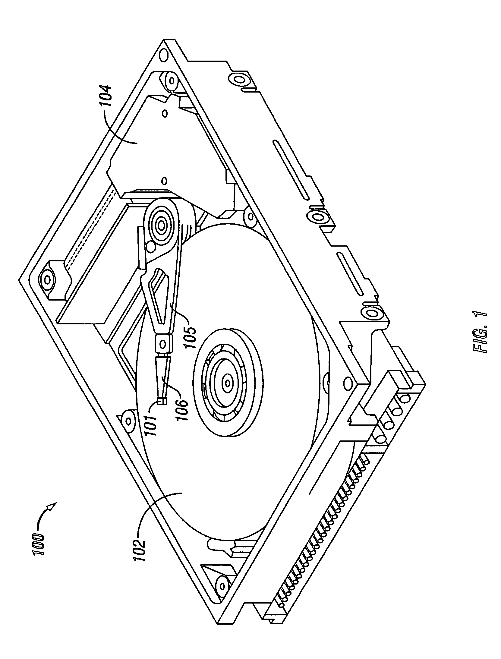
BACKGROUND OF THE INVENTION[0001]1. Field of the Invention[0002]The present invention relates to Hard Disk Drives (HDDs). More particularly, the present invention relates to a technique for controlling the spacing between the pole tips of a write element and a magnetic medium (i.e., the flying height of a slider) of an HDD in a linear manner using a control signal.[0003]2. Description of the Related Art[0004]FIG. 1 shows an exemplary hard disk drive (HDD) 100 having a servo system for positioning a slider assembly 101 over a selected data information track on a magnetic disk 102 for writing data to and / or reading data from the selected track. The servo system of HDD 100 includes an actuator 104, such as a rotary voice-coil motor (VCM), for positioning an actuator arm 105, a read / write head suspension 106 and slider assembly 101 over a selected track. Slider assembly 101 includes a read / write head (not shown in FIG. 1) having a read element, such as a Giant Magnetoresistive (GMR) ele...

Claims


Application Information

Patent Timeline
Patent Type & Authority Patents(United States)
IPC IPC(8): G11B5/60G11B21/02G11B21/21
CPCG11B5/6064G11B5/6005G11B5/607
Inventor CONTERAS, JOHN THOMASKLAASSEN, KLAAS BERENDVAN PEPPEN, JACOBUS CORNELIS LEONARDUS
Owner WESTERN DIGITAL TECH INC
Learn More