
System and method for protecting an audio amplifier output stage power transistor

a technology of audio amplifiers and power transistors, applied in the direction of push-pull amplifiers, emergency protective arrangements for limiting excess voltage/current, single-ended push-pull amplifiers, etc., can solve problems such as power transistor failure, power transistor failure, transistor failure, etc., to reduce the complexity of the circuit required

Active Publication Date: 2006-06-13
GIBSON BRANDS
View PDF10 Cites 5 Cited by
  • Summary
  • Abstract
  • Description
  • Claims
  • Application Information

AI Technical Summary

Benefits of technology

[0041]Accordingly, one object of the present invention is to provide a system and method of protecting an audio amplifier output stage power transistor that does not interfere with the normal operation of that transistor.
[0042]Another object of the present invention is to provide a system and method for generating a protection threshold for a power transistor that tracks the operating characteristics of that transistor more accurately than prior art protection circuits.
[0044]Still another object is to provide a system and method for generating a protection threshold for a power transistor that allows the power transistor to temporarily exceed its steady state operating limits.
[0045]Yet another object of the present invention is to provide a system and method of protecting an audio amplifier output stage power transistor that is less complex and easier to implement than the protection circuit taught by the '809 patent.
[0050]Inherent in the method discussed above, is a new method of calculating the junction temperature of a power transistor. More specifically, the steps of generating the estimate of the power dissipation by the power transistor, the varying of that estimate as a function of the power transistor temperature, and the filtering of that time varying estimate generates a signal that is representative of the junction temperature of the power transistor. Significantly, the junction temperature signal is calculated without using a multiplier, which reduces the complexity of the circuit required to generate the signal.

Problems solved by technology

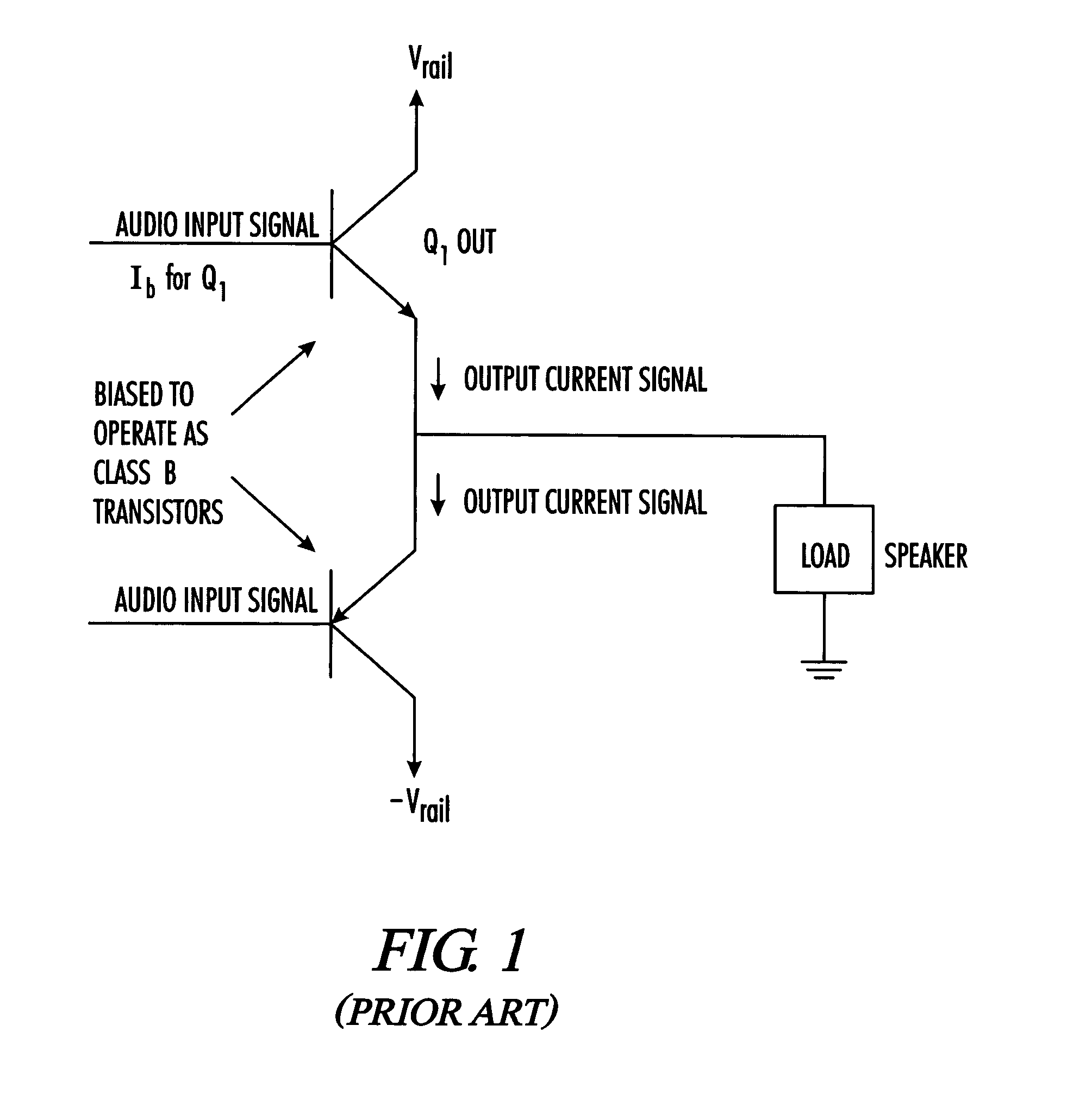
It is noted, however, that Class A, Class AB, Class G, Class H, and other types of output stages known in the art, suffer from problems similar to the ones discussed below with regard to Class B output stages.
The power transistors used in the output stage of the audio amplifier shown in FIG. 1 can only be operated under certain conditions or they will fail.
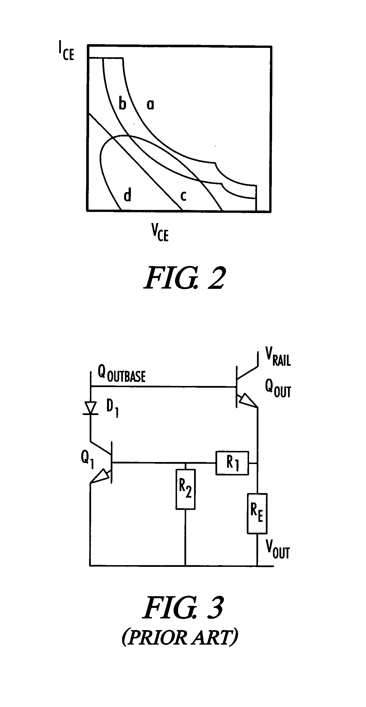
If any of these limits are exceeded, the power transistors can fail.
If these parameters are exceeded for too long, however, the transistor will fail.
First, power transistors typically fail because of excessive heating, which is, in turn, caused by excessive voltage and current.
Second, power transistors have thermal impedance and, as a result, it takes a certain amount of time for the transistor to heat up to the point where it is damaged.
If the transistor is operated above the SOA for a predetermined time period, the transistor will fail.
If a short circuit occurs, however, Ice will increase significantly and generate a large voltage on RE.
While current limiter circuits do limit the amount of current output by power transistors, they also interfere with the normal operation of the very power transistors they are designed to protect.
Unfortunately, the protection circuit also prevents the transistor from operating in portions of the SOAs associated with lines a and b. In other words, the current limiter prevents the power transistor from operating in areas where it can safety operate.
As was the case with the simple current limiter, the VI limiter circuit also interferes with the normal operation of the power transistors it is designed to protect.
A power transistor connected to this type of protection circuit cannot operate in the area above line e and this prevents the transistor from operating in a portion of its SOA.
Once again, this type of operation is undesirable for the same reason as that discussed above for the simple current limiter.
Although the two slope VI limiter protection circuit is an improvement over the single slope VI limiter and the simple current limiter, it still interferes with the normal operation of the power transistor it is designed to protect.
While all of the prior art protection circuits discussed above do protect the power transistor when properly used, they also unnecessarily interfere with the normal operation of the power transistor.
As a result, the protection thresholds do not accurately track the operating characteristics of the power transistor and prevent the power transistor from operating in areas it normally would be able to operate.
As the temperature decreases, the operating limits increase.
Thus, prior art protection circuits interfere with the normal operation of power transistors for this reason as well.
Regardless of the reason, the interference with normal power transistor operation is an undesirable condition.
When the prior art protection circuits limit a power transistor as discussed above, the power transistor can no longer generate an output current that is representative of the audio input signal and, as a result, the speaker no longer accurately reproduces the sounds associated with the audio input signal.
The power transistor die is the portion of a power transistor that can be damaged by excessive heat and cause the power transistor to fail.
The protection circuit taught in the '809 patent, however, is a complex circuit and can be difficult to implement in practice.
As a result, this protection is undesirable in some applications.

Method used


Image

  • System and method for protecting an audio amplifier output stage power transistor
  • System and method for protecting an audio amplifier output stage power transistor
  • System and method for protecting an audio amplifier output stage power transistor

Examples


Embodiment Construction

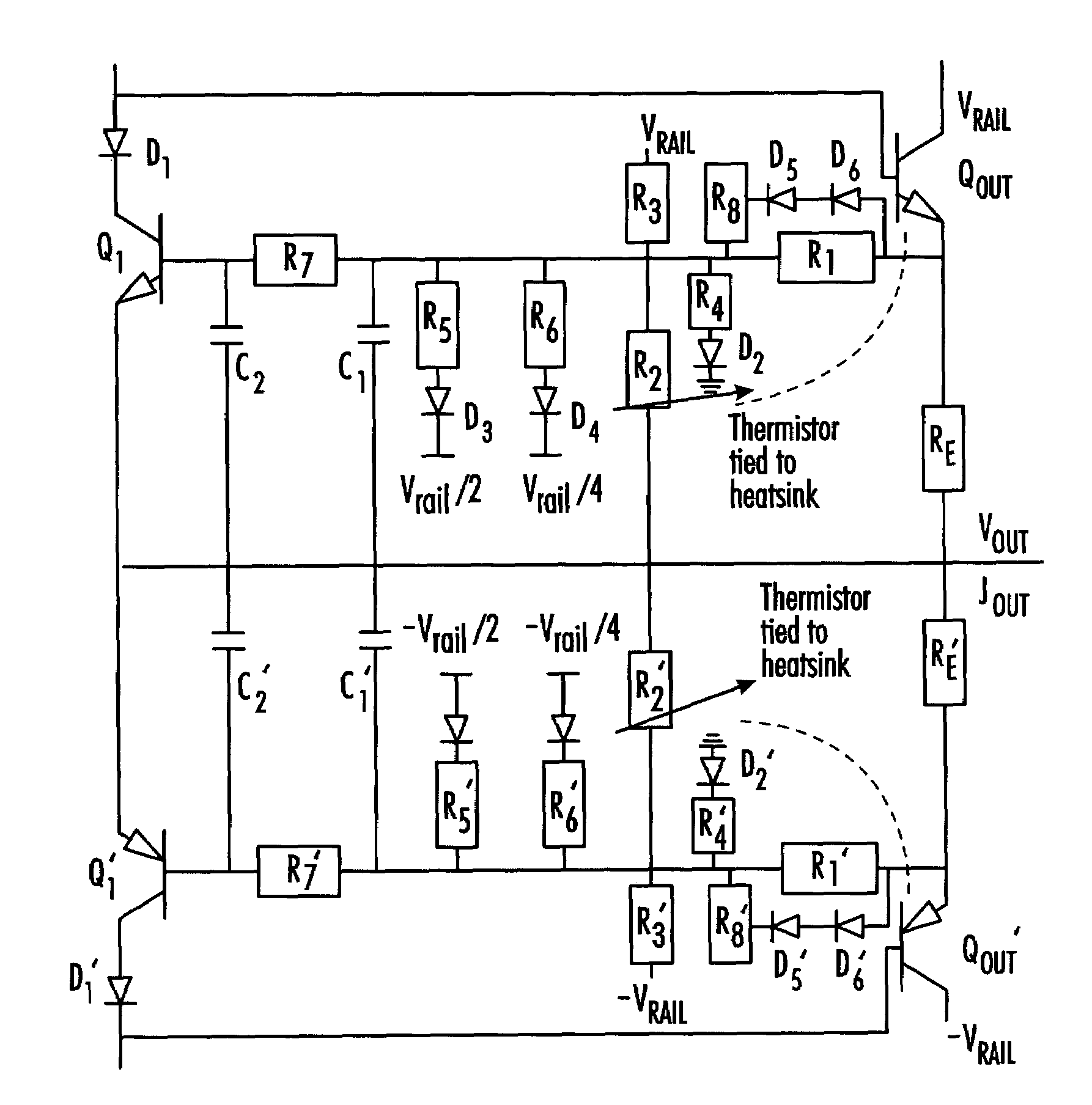
[0070]Referring to FIG. 9, one embodiment of the protection circuit 10 of the present invention includes a transistor power estimation circuit 12, a power estimate filtering circuit 14, a transistor control circuit 16, a transistor temperature adjustment circuit 18, and a transistor maximum current limiting circuit 20. The protection circuit 10 protects the audio amplifier output stage power transistor 22 by sensing the operating power of transistor 22 and modifying its input signals so that the operating power does not exceed a predetermined operating power limit.

[0071]Referring to FIG. 10, the transistor power estimation circuit 12 generates an estimate of the power dissipation of transistor 22. To accomplish this function, the circuit 12 includes a power transistor current sensing circuit 24, a power transistor voltage sensing circuit 26, and a summing circuit 28. Both circuits, 24 and 26, are connected to the output of the power transistor 22 and to the summing circuit 28. The c...


PUM


Abstract

A system and method for protecting an output transistor in an audio amplifier output stage includes a protection circuit that protects the output transistor from excessive currents and voltages, and does not interfere with the normal operation of the output transistor. The protection circuit generates an estimate of the power dissipated by the output transistor, applies this estimate to an electrical analog of the thermal time constants of the transistor to obtain an estimate of the temperature differential between junction and case, compares this differential to a limit, which is a function of transistor case temperature.

Description

[0001]This application is a Non-Provisional Utility application that claims benefit of co-pending U.S. Patent Application, Ser. No. 60 / 391,650 filed Jun. 26, 2002, entitled “Audio Power Amplifier Output Stage Protection” which is hereby incorporated by reference.[0002]A portion of the disclosure of this patent document contains material that is subject to copyright protection. The copyright owner has no objection to the facsimile reproduction by anyone of the patent document or the patent disclosure, as it appears in the Patent and Trademark office patent file or records, but otherwise reserves all copyright rights whatsoever.[0003]Be it known that I, Eric Mendenhall, a citizen of the United States, residing in Dove Canyon, Calif., have invented a new and useful “System And Method For Protecting An Audio Amplifier Output Stage Power Transistor.”BACKGROUND OF THE INVENTION[0004]The present invention relates generally to audio power amplifiers. More particularly, this invention pertai...

Claims


Application Information

Patent Timeline
Patent Type & Authority Patents(United States)
IPC IPC(8): H02H3/08H02H9/02H03F1/52H03F3/30
CPCH03F3/3069H03F1/52
Inventor MENDENHALL, ERIC
Owner GIBSON BRANDS
Learn More