Digital video recording apparatus

a video recording and digital technology, applied in the field of digital video recording apparatus, can solve the problems of mismatch between, data should be frequently written onto the recording medium, and video data in the stream file may not be managed by the management information

Active Publication Date: 2006-06-13
PANASONIC CORP
View PDF18 Cites 15 Cited by
  • Summary
  • Abstract
  • Description
  • Claims
  • Application Information

AI Technical Summary

Benefits of technology

[0011]It is therefore an object of the present invention to provide a digital video recording apparatus that eliminates a mismatch that occurs between a stream file and the management information when a writing error or a power failure occurs during recording of video data, without allowing the stream files to always coordinate with the management information, and recovers the video data, which is stored in a stream file but cannot be played back by conventional methods, as much as possible so as to play back the recovered video data.

Problems solved by technology

However, if a writing error or a power failure occurs during recording of video data, a mismatch occurs between a file storing the recorded video data (hereinafter referred to as stream file) and the management information.
Also, in such a case, a stream file may be successfully recorded onto a recording medium, but the video data in the stream file may not be managed by the management information.
This method, however, has another problem that data should be frequently written onto the recording medium.

Method used


Image

  • Digital video recording apparatus
  • Digital video recording apparatus
  • Digital video recording apparatus

Examples


embodiment 1

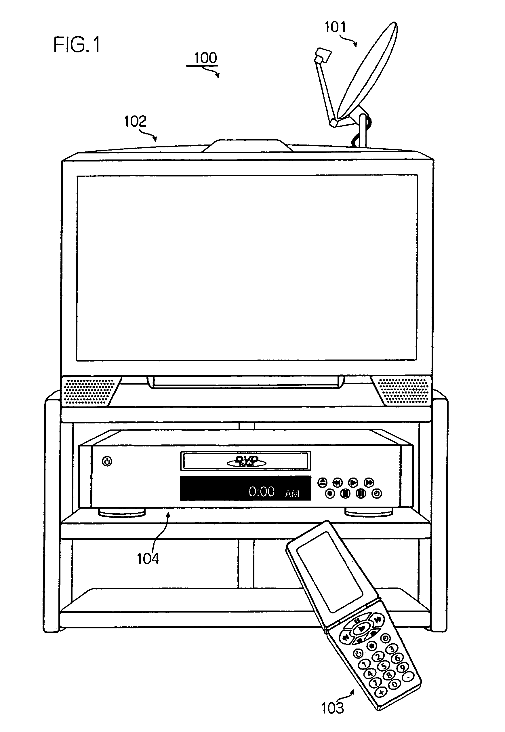
[0056]FIG. 1 is a schematic representation of an audio visual system including the digital video recording apparatus of the present invention.

[0057]As shown in FIG. 1, the audio visual system (hereinafter referred to as AV system) 100 is composed of an antenna 101, a monitor 102, a remote controller 103, and the digital video recording apparatus 104.

[0058]The antenna 101 receives broadcast programs (hereinafter referred to as programs) transmitted from a broadcasting station, and sends the received programs to the monitor 102 and the digital video recording apparatus 104.

[0059]It should be noted here that the programs are broadcast in analog form and that each program contains audio signals and video signals.

[0060]The monitor 102 displays the programs received by the antenna 101 and audio signals and video signals (hereinafter referred to as audio-video signals) output from the digital video recording apparatus 104.

[0061]The remote controller 103 has operation keys and a display pan...

embodiment 2

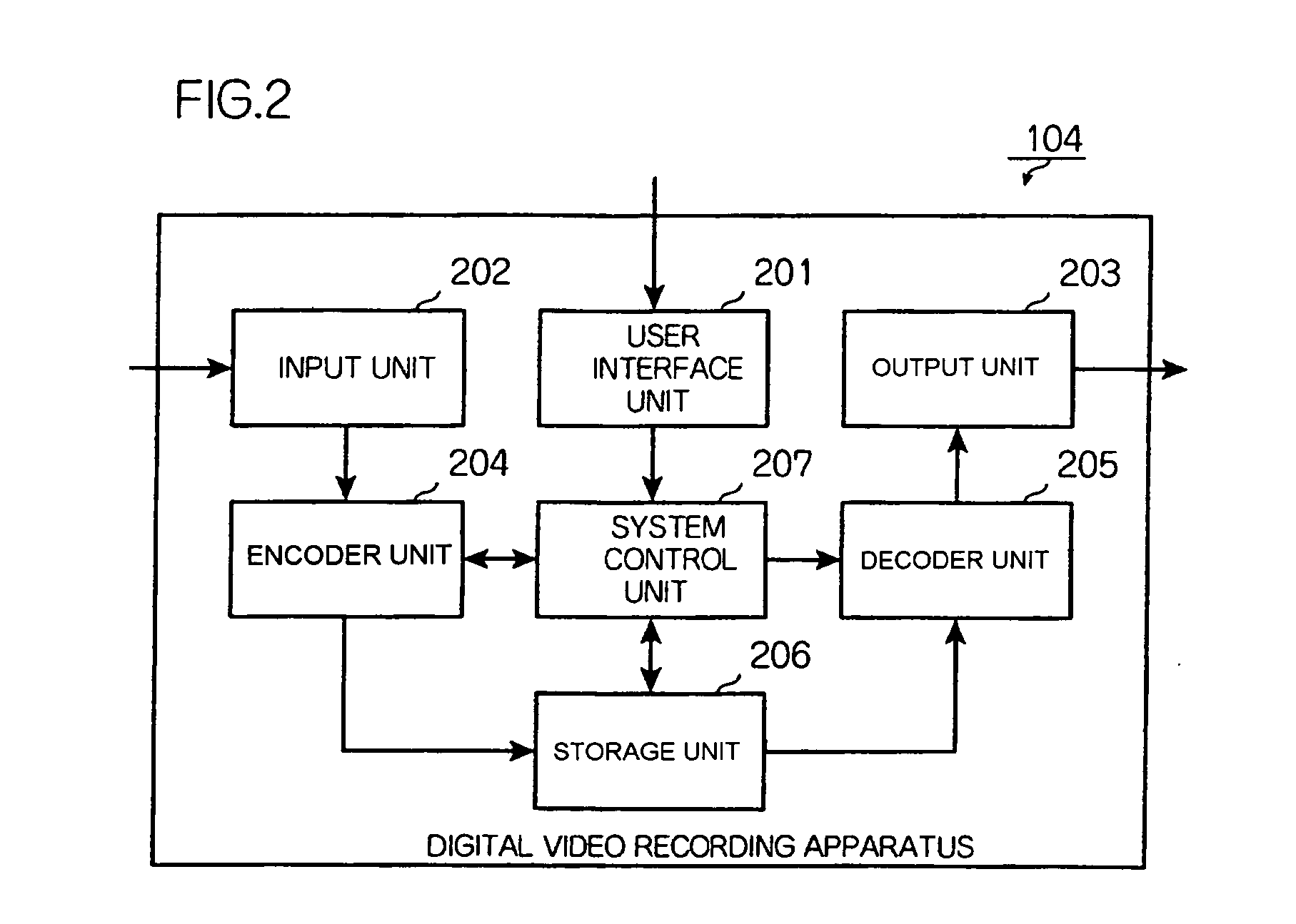
[0171]The following is a description of the digital video recording apparatus in Embodiment 2 which includes the same components as Embodiment 1 with the same reference numbers and such components will not be detailed here. The following description will focus on components different from those in Embodiment 1.

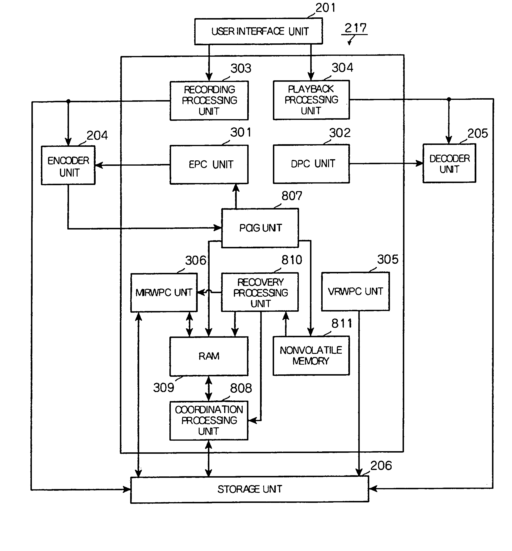
[0172]FIG. 8 is a block diagram showing functions of the system control unit in Embodiment 2.

[0173]As shown in FIG. 8, the system control unit 217 is different from the system control unit 207 in Embodiment 1 in that it has a playback control information generating unit 807 and a coordination processing unit 808 instead of the playback control information generating unit 307 and the coordination processing unit 308, and that it further includes a recovery processing unit 810 and a nonvolatile memory 811.

[0174]The playback control information generating unit 807 is different from the playback control information generating unit 307 in that it generates saving data as a recordin...


PUM

PropertyMeasurementUnit
sizeaaaaaaaaaa
sizesaaaaaaaaaa
data structureaaaaaaaaaa

Abstract

A recording apparatus that records video data and corresponding playback control information onto a recording medium includes a recovery processing unit detects whether an abnormality occurred and stopped recording of video data, and if it detects the abnormality, it generates playback control information corresponding to the video data having been recorded on the recording medium up to the point when the abnormality occurred, where the playback control information controls playback operation of a playback apparatus, and the abnormality indicates that a recording of video data abnormally stopped and corresponding playback control information was not recorded onto the recording medium.

Description

BACKGROUND OF THE INVENTION[0001](1) Field of the Invention[0002]The present invention relates to a digital video recording apparatus that upon occurrence of a writing error or a power failure, makes video data stored in a recording medium coordinate with management information managing the video data, during the recovery operation.[0003](2) Description of Related Art[0004]Conventional VCRs record video data continuously on tape. In this recording method, the recording order of video data on tape is used as the playback order as it is, and any special information is not required for management of the playback order of the recorded video data.[0005]VCRs in recent years, however, record management information such as marks like VISS together with video data so that the starts of recorded sequences can be located.[0006]With the above construction, if a writing error or a power failure occurs during recording of video data, both the video data and the management information are recorded...

Claims


Application Information

Patent Timeline
Patent Type & Authority Patents(United States)
IPC IPC(8): H04N7/64H04N5/91H04N19/89G11B19/04G11B27/034G11B27/10G11B27/11G11B27/32G11B27/36H04N5/781H04N5/85H04N9/804
CPCG11B27/034G11B27/105G11B27/11G11B27/329G11B27/36G11B19/04H04N9/8042G11B2220/216G11B2220/2575G11B2220/65H04N5/781H04N5/85G11B2220/2562
Inventor NAKATANI, TOKUONAKAMURA, KAZUHIKO
Owner PANASONIC CORP
Why Eureka
Try Eureka