
Method and apparatus for frequency synchronization in a digital transmission system

a digital transmission system and frequency synchronization technology, applied in the direction of transmission monitoring, frequency-division multiplex, synchronisation signal speed/phase control, etc., can solve the problems of filter parameters going out of bounds, delay affecting the fcch detection algorithm,

Inactive Publication Date: 2006-06-13
MEDIATEK INC
View PDF9 Cites 31 Cited by
  • Summary
  • Abstract
  • Description
  • Claims
  • Application Information

AI Technical Summary

Benefits of technology

The present invention provides methods for detecting and synchronizing signals in a digital transmission network. These methods involve analyzing signals that include a frequency correction tone to enable a receiver to synchronize with the sender. The methods involve correlating received samples of the signals and averaging them using a moving average to generate a revenue function. The revenue function is then compared with a threshold to detect the frequency correction tone. After detecting the frequency correction tone, the methods estimate a timing offset by searching for a peak position of the revenue function. These methods allow for more accurate and efficient synchronization in digital transmission networks.

Problems solved by technology

That patent's strategy relies on pre-processing to provide signal de-rotation via table lookup and uses a large memory to perform the de-rotation, which can be undesirable if it impacts on the speed with which the synchronization tone is acquired.
The transient processing of the training phase of the adaptive filtering may introduce a delay that could affect the FCCH detection algorithm.
Furthermore the filter parameters may go out of bounds after several TDMA frames of unsuccessful detection so that the FCCH might not be detected.

Method used


Image

  • Method and apparatus for frequency synchronization in a digital transmission system
  • Method and apparatus for frequency synchronization in a digital transmission system
  • Method and apparatus for frequency synchronization in a digital transmission system

Examples


Embodiment Construction

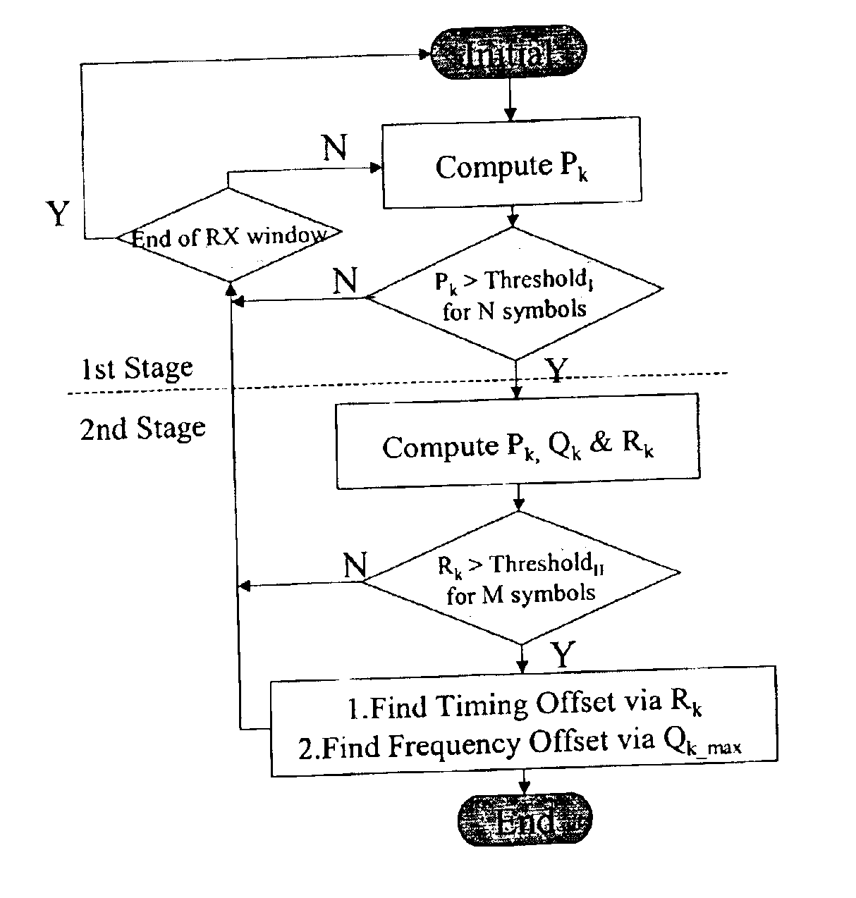
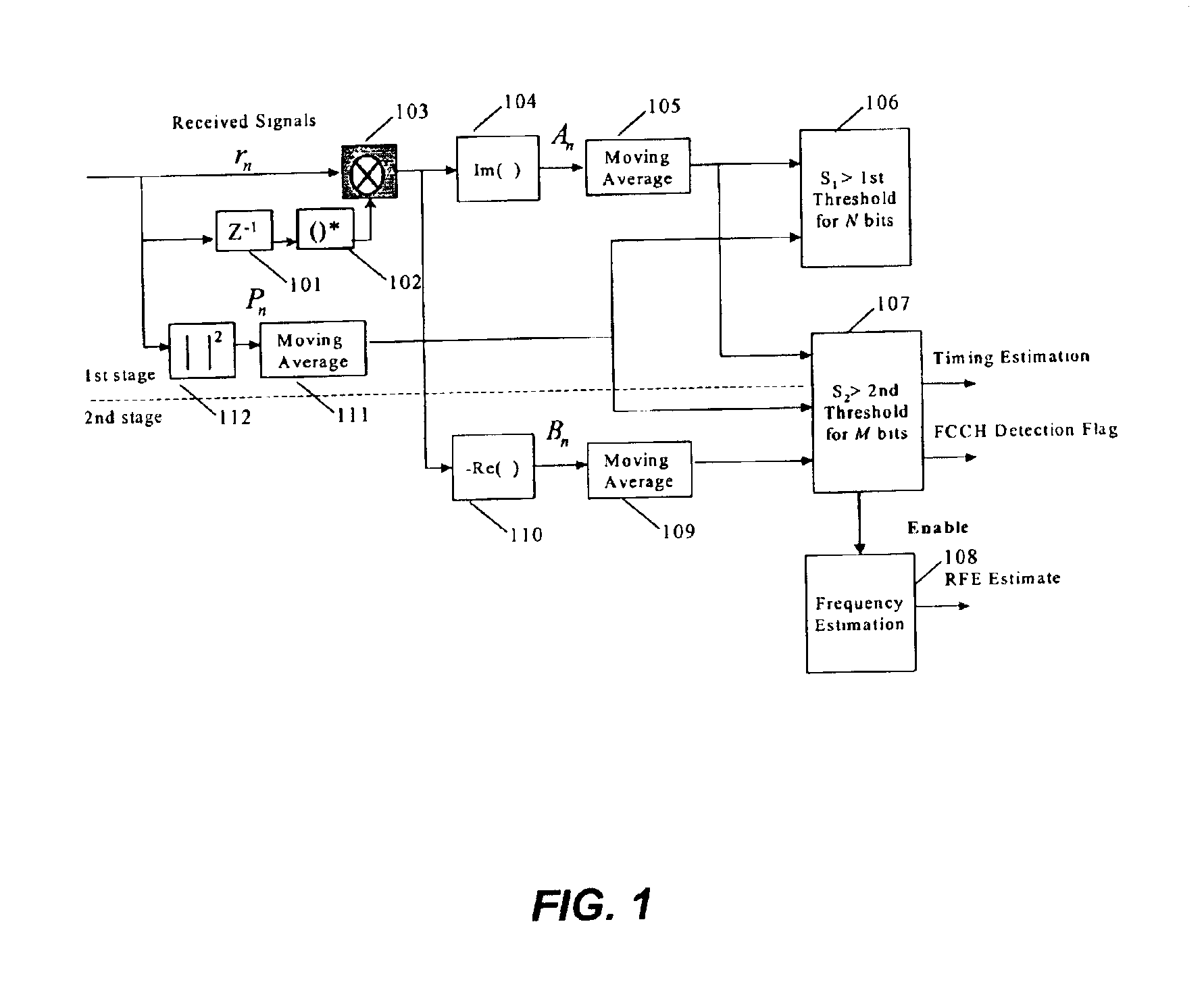
[0007]An aspect of the present invention provides a method of detecting a frequency synchronization signal for a digital transmission network in which a sender transmits a plurality of signals including a frequency correction tone so that a receiver can synchronize with the sender. The method includes correlating received samples of a plurality of signals (which can be referred to as signal symbols) including a frequency correction tone and averaging the correlated symbols using a moving average over a sliding window to generate at least a portion of a revenue function. An average power of the received signals is calculated for normalizing the revenue function. The method determines whether the frequency correction tone is present by comparing the revenue function with a threshold and observing that the revenue function exceeds the threshold for a number of contiguous symbols. After the frequency correction toned is detected, the method estimates a timing offset by searching for a p...


PUM


Abstract

Frequency synchronization bursts are detected for a radio communication system such as a GSM cellular telephone network using a two stage correlation process. A first unit performs a first set of correlations to identify receipt of the frequency synchronization burst. A preliminary identification is declared when the moving average of the first set of correlations, normalized for received power, exceeds a threshold value for a number of contiguous samples. After a preliminary identification is made, a second unit performs a second set of correlations to confirm the detection of the frequency synchronization burst. The second correlations are preferably also normalized and confirmation of detection is declared when the normalized moving average of the second stage correlation exceeds a threshold value for a number of contiguous samples.

Description

BACKGROUND OF THE INVENTION[0001]1. Field of the Invention[0002]This invention generally relates to pilot tone acquisition and timing offset estimation in a wireless communication system such as that used for cellular telephony. It provides a method and apparatus for detecting a synchronization signal from the radio propagation channels with sufficiently high probability as well as an acceptably low false alarm rate even in the presence of a large frequency deviation at the receiving side. In addition, aspects of the present invention locate the timing boundary of the incoming data stream in a digital transmission system by detecting the pilot tone.[0003]2. Description of the Related Art[0004]In a mobile communication system having a pilot channel, a mobile station (MS) synchronizes with the base station (BS) via a pilot channel so that information can be exchanged and a communication link can be established successfully. Since the mobile station generally does not have a sufficient...

Claims


Application Information

Patent Timeline
Patent Type & Authority Patents(United States)
IPC IPC(8): H04B7/005H04J1/00H04L7/04
CPCH04L7/042Y10S707/99955Y10S707/99953H04L2007/047
Inventor LIU, SHANG-CHIEHSUN, WEI-NANHWANG, HO-CHI
Owner MEDIATEK INC
Learn More