Method for forming permanent magnet targets for position sensors

a technology of position sensors and permanent magnets, applied in the field of position sensors, can solve the problems of limiting the durability of contact-type position sensors, inaccurate position sensors affecting the proper position evaluation and control of moving components, and manufacturing methods that are not only expensive, but also unsuitable for manufacturing targets. , to achieve the effect of improving the accuracy of position detection and precise positioning of targets

Inactive Publication Date: 2006-06-20
DELPHI TECH INC
View PDF14 Cites 3 Cited by
  • Summary
  • Abstract
  • Description
  • Claims
  • Application Information

AI Technical Summary

Benefits of technology

[0013]The target is employed with a magnetic field sensor that produces an output signal representative of the position of the magnetic field (without the use of a bias magnet as required by the prior art), which is in turn representative of the position of the target track. The precision of the position detection is improved by the target track's straight vertical sidewalls and the precise positioning of the target resulting from use of the photolithographic process.

Problems solved by technology

Motion-induced contact wear limits the durability of the contact-type position sensors.
An inaccurate position sensor hinders the proper position evaluation and control of the moving component.
These manufacturing methods are not only expensive, but are also not suitable for manufacturing targets with fine features and complex geometries that are required for high-accuracy small target sensors.
Asymmetries in the placement of the teeth in a target wheel or changes in gap distance as the target wheel rotates cause inaccuracies in position determination.
Although it is possible to manufacture precise continuous sensors using the prior art techniques of machining, stamping, etc. described above, precision equipment is required and thus the cost for such sensors is high.

Method used


Image

  • Method for forming permanent magnet targets for position sensors
  • Method for forming permanent magnet targets for position sensors
  • Method for forming permanent magnet targets for position sensors

Examples


Embodiment Construction

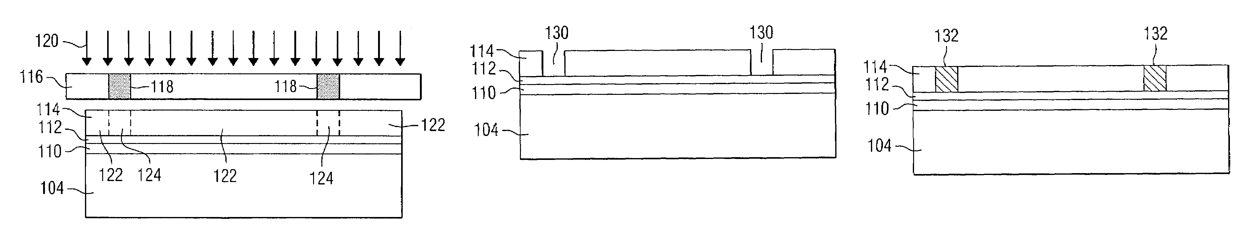
[0025]Before describing in detail the particular method for forming targets for position and speed sensors and targets formed according to said methods in accordance with the teachings of the present invention, it should be observed that the present invention resides primarily in a novel and non-obvious combination of hardware elements and process steps related to forming said targets. Accordingly, the hardware elements and method steps have been represented by conventional elements in the specification and the drawings, showing only those specific details that are pertinent to the present invention, so as not to obscure the disclosure with structural details that will be readily apparent to those skilled in the art having the benefit of the description herein.

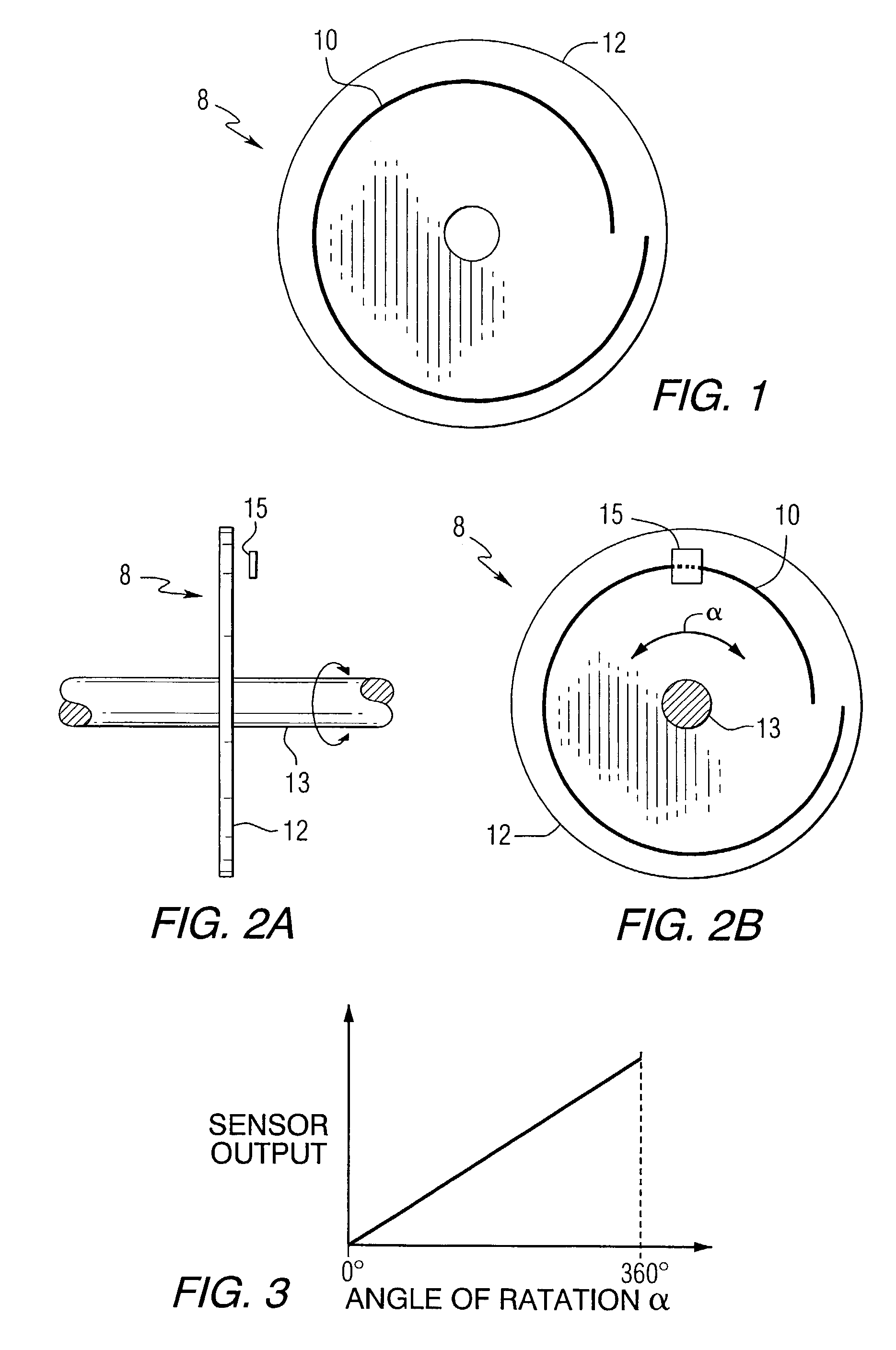
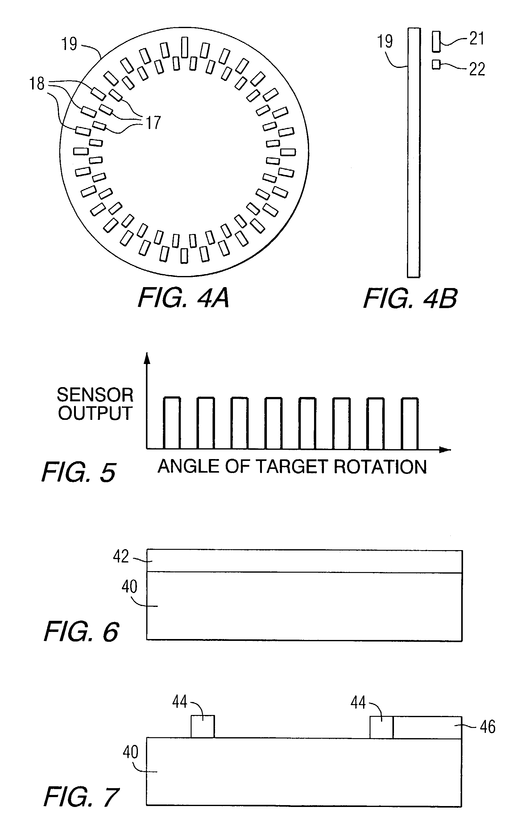
[0026]Advantageously, according to the teachings of the present invention, the target includes permanent magnetic material in lieu of the prior art ferromagnetic material. The magnetic field sensing can be performed by a Hall ...


PUM

PropertyMeasurementUnit
angular rotationaaaaaaaaaa
thickaaaaaaaaaa
thickaaaaaaaaaa

Abstract

A process for forming magnetic targets for position and speed sensors, and magnetic targets formed according to the process. The targets are formed on a conductor-clad substrate by first applying a layer of photoresist material and then patterning and etching the photoresist to form trenches defining the shape and dimensions of the targets. Magnetic material is formed in the trenches and magnetized to form the targets.

Description

TECHNICAL FIELD[0001]The present invention relates generally to position sensors, and more specifically to a method for forming permanent magnet targets for position sensors that provide the required degree of accuracy and resolution of the sensed position, and target apparatus formed thereby.BACKGROUND OF THE INVENTION[0002]Position sensors monitor the position or motion of a first mechanical component relative to a second mechanical component, by producing an electrical signal that varies as a function of the relative position of the two components. The relative speed of the two components can also be determined by taking the time derivative of the position Electrical position sensors are an important part of innumerable products, and are useful for determining the status of various automotive actuations and processes that involve either linear or angular displacement. For example, the position of an adjustable automotive seat can be determined by sensing devices mounted in the mo...

Claims


Application Information

Patent Timeline
Patent Type & Authority Patents(United States)
IPC IPC(8): H01F7/06C25D5/02H01F41/14G01D5/14H01F10/06H01F10/16H01F10/30H01F13/00H01F41/26H01F41/34H05K1/02H05K1/16H05K3/10
CPCG01D5/145H01F10/06H01F41/14H01F41/26H01F41/34H05K1/0233Y10T29/49156H05K3/108Y10S428/90Y10T29/49032Y10T29/49075Y10T29/4902Y10T29/49069H05K1/165G01D2205/773G01D2205/80
Inventor SCHROEDER, THADDEUSCHANG, SHIH-CHIARODRIGUEZ, LORENZO GUADALUPE
Owner DELPHI TECH INC
Why Eureka
Try Eureka