Diffuser arrangement

a diffusion arrangement and diffuser technology, applied in the direction of machines/engines, stators, mechanical apparatuses, etc., can solve the problems of not being able to achieve desired, requiring higher diffusion rates, and diffusion arrangements that are difficult to incorporate within the desired engine length, etc., to facilitate flow bleed

Inactive Publication Date: 2006-06-20
ROLLS ROYCE PLC
View PDF16 Cites 30 Cited by
  • Summary
  • Abstract
  • Description
  • Claims
  • Application Information

AI Technical Summary

Benefits of technology

[0005]In accordance with the present invention there is provided a diffuser arrangement for an engine, the arrangement comprising a wall surface in a fluid flow conduit and formed with an aperture between an upstream part of the wall surface and a down...

Problems solved by technology

Initially, divergence ducts were provided in order to achieve diffusion but these may not be able to achieve desired and required higher rates of diffusion whilst the flow remains attached.
It should also be understood that it is desira...

Method used


Image

  • Diffuser arrangement
  • Diffuser arrangement
  • Diffuser arrangement

Examples


Embodiment Construction

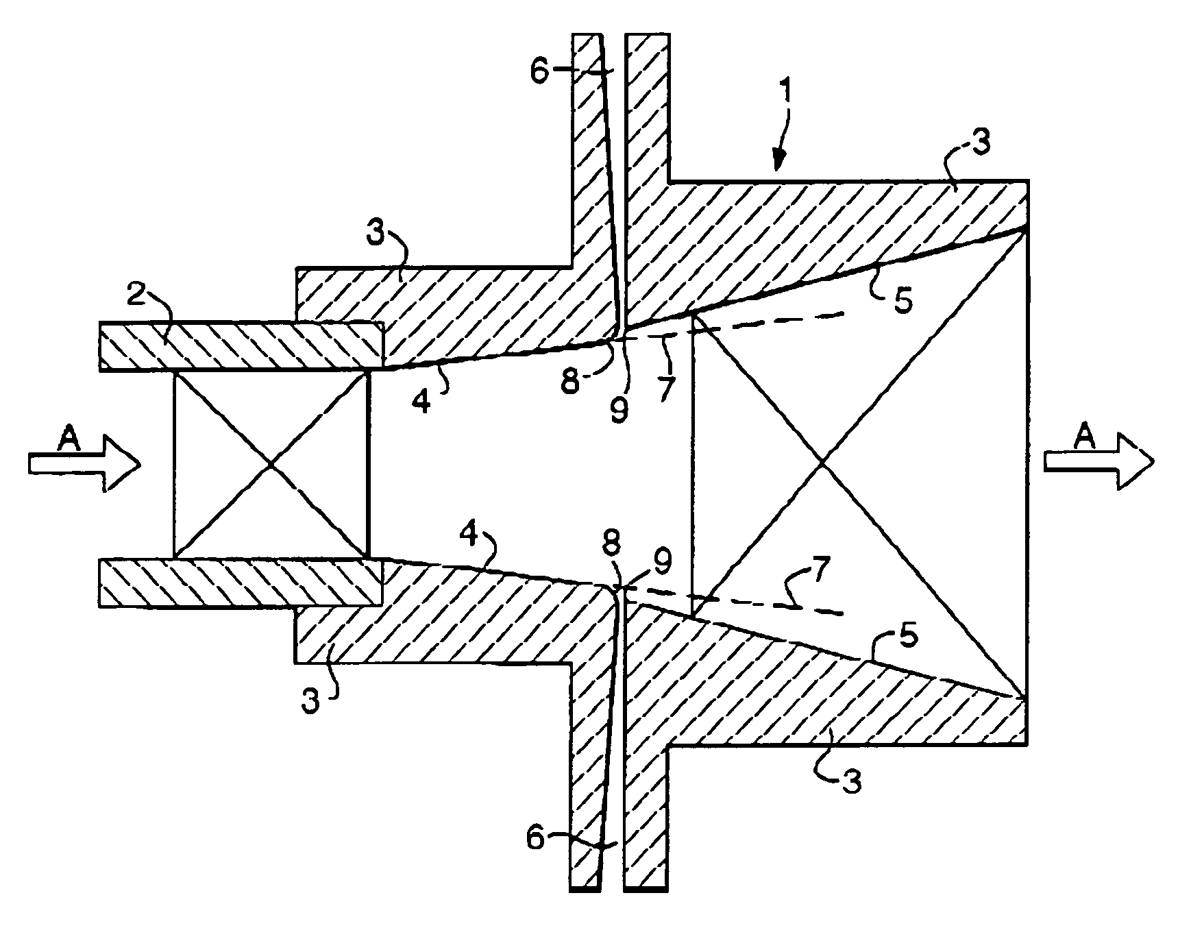
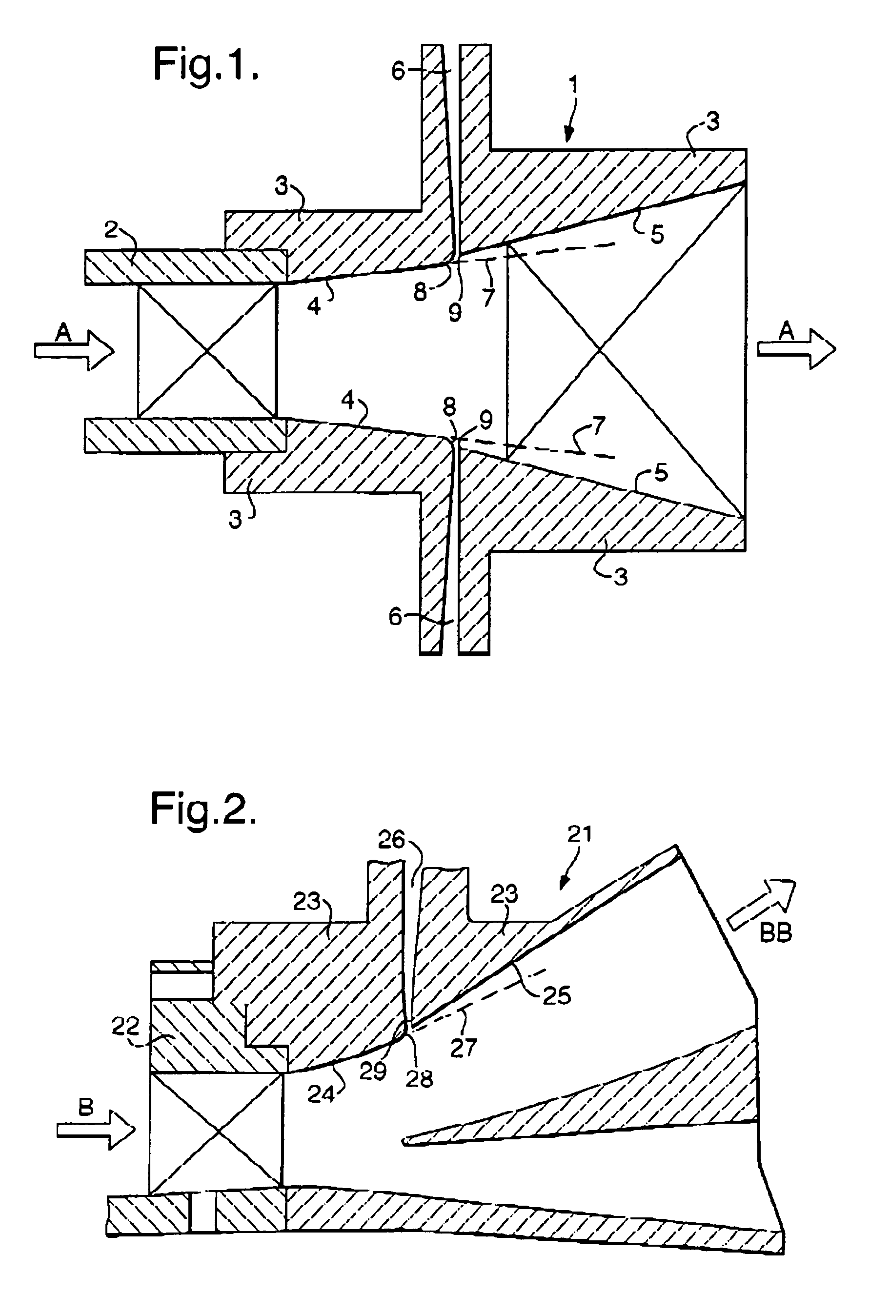
[0022]Referring to FIG. 1 which depicts a schematic cross-section of a diffuser arrangement 1 in accordance with the present invention. Thus, the diffuser arrangement 1 includes an inlet 2 which presents a fluid or air flow in the direction of arrow head A to the diffuser arrangement 1. The arrangement incorporates wall surfaces 3 which in turn comprise an upstream part 4 and a downstream part 5 divided by an aperture 6 between these parts 4, 5. In such circumstances, the fluid air flow in the direction of arrow head A passes through the inlet 2 and out of the arrangement 1 with a proportion of that fluid air flow bled or diffused through the aperture 6. This diffused or bled air taken through the aperture 6 is utilised for cooling etc in other parts of the engine.

[0023]In accordance with the invention, the upstream parts 4 are presented such that a projected profile depicted by broken lines 7 which is a continuation of the upstream part 4 surface is not consistent with the extendin...


PUM


Abstract

A diffuser arrangement is provided in which a wall surface of the diffuser arrangement incorporates an upstream part and a downstream part with an aperture between them. There is a step displacement between the upstream part and the downstream part along with specific shaping of the leading edge of the aperture whereby fluid air flow is drawn into the aperture from a fluid flow whilst avoiding undue disturbance to that flow. The present diffuser arrangement allows incorporation within an engine without complex fabrication or structural requirements.

Description

FIELD OF THE INVENTION[0001]The present invention relates to diffuser arrangements and more particularly to diffuser arrangements used within gas turbine engines which utilise bleed in order to increase area ratios and divergence angles within a given length and that the bleed air can then be utilised for component cooling.BACKGROUND OF THE INVENTION[0002]Within a gas turbine engine it will be appreciated that a compressor stage presents an airflow to a combustion chamber where high temperatures and gas flows allow a turbine system to drive the engine. In order to achieve stable and efficient combustion it is desirable to ensure that there is a suitable air flow within the combustion stage. In such circumstances, a diffuser arrangement is provided in order to reduce airflow velocity and increase static pressure. In general terms, air is diffused or bled from the output compressor air flow. This diffused air is utilised for cooling and other purposes about the engine.[0003]It is impo...

Claims


Application Information

Patent Timeline
IPC IPC(8): F02C3/00F02C7/18F01D9/02F01D9/04
CPCF01D9/04F01D9/02
Inventor WALKER, ALASTAIR DDENMAN, PAUL A
Owner ROLLS ROYCE PLC
Why Eureka
Try Eureka