Dual clutch assembly for a motor vehicle powertrain

a technology of clutches and motor vehicles, applied in the direction of mechanical actuated clutches, interengaging clutches, gearing, etc., can solve the problems of increasing the deflection of the crankshaft and increasing the load on the system, increasing the deflection of the crankshaft and resulting load, and irregular wear of the friction discs of the clutches. to achieve the effect of less mass

Inactive Publication Date: 2006-06-20
FORD GLOBAL TECH LLC
View PDF22 Cites 57 Cited by
  • Summary
  • Abstract
  • Description
  • Claims
  • Application Information

AI Technical Summary

Benefits of technology

[0009]A clutch assembly according to this invention requires less mass, rotating inertia and packaging space compared to conventional clutch support arrangements.
[0010]The entire clutch assembly mass is fully supported on an output shaft of the power source and by bearings or bushings mounted on a transmission housing. This mounting arrangement provides stable support for the clutch and reduces the effects of crankshaft whirl and misalignment of the crankshaft relative to the transmission. Powertrain noise, vibration, and harshness are improved due to the reduction in first order imbalance forces.
[0011]Engine power is transmitted to the clutch system by a flexible disc or coupling that allows for radial and angular misalignment of the engine crankshaft relative to the clutch assembly. The flexible disc, however, provides sufficient axial strength to transmit clutch actuation forces to a crankshaft thrust bearing as well as to transmit torque between the crankshaft and the clutch.

Problems solved by technology

The resulting orbiting radius from the crankshaft axis and the clutch mass together induce a first order forced vibration in the powertrain, which further increases crankshaft deflection and increases load on the system.
Misalignment of the engine crankshaft centerline relative to the transmission input shaft centerline causes the surfaces of the friction discs of the clutch to wear irregularly in compliance with the misalignment.
Misalignment of the clutch mass relative to the crankshaft during initial installation also contributes to the problem.
The resulting orbit radius and the torque converter mass induce a first order vibration in the powertrain, which increases the crankshaft deflection and resulting loads.
Misalignment of the torque converter mass relative to the crankshaft during installation and misalignment of the transmission support relative to the engine crankshaft centerline contribute to the vibration.

Method used


Image

  • Dual clutch assembly for a motor vehicle powertrain
  • Dual clutch assembly for a motor vehicle powertrain
  • Dual clutch assembly for a motor vehicle powertrain

Examples


Embodiment Construction

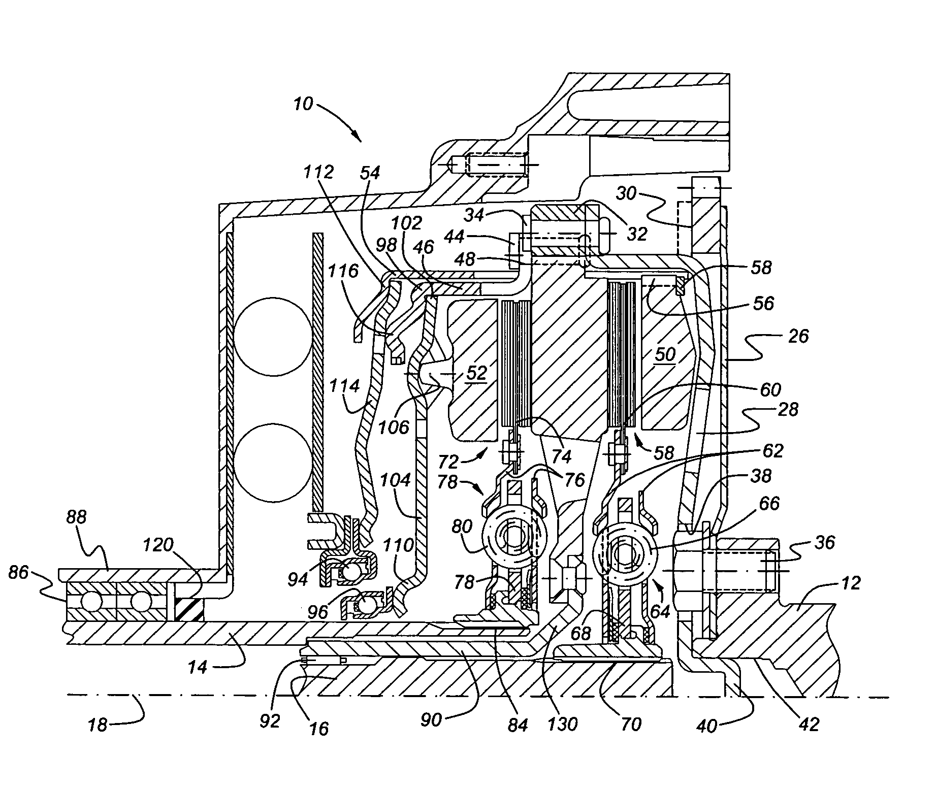
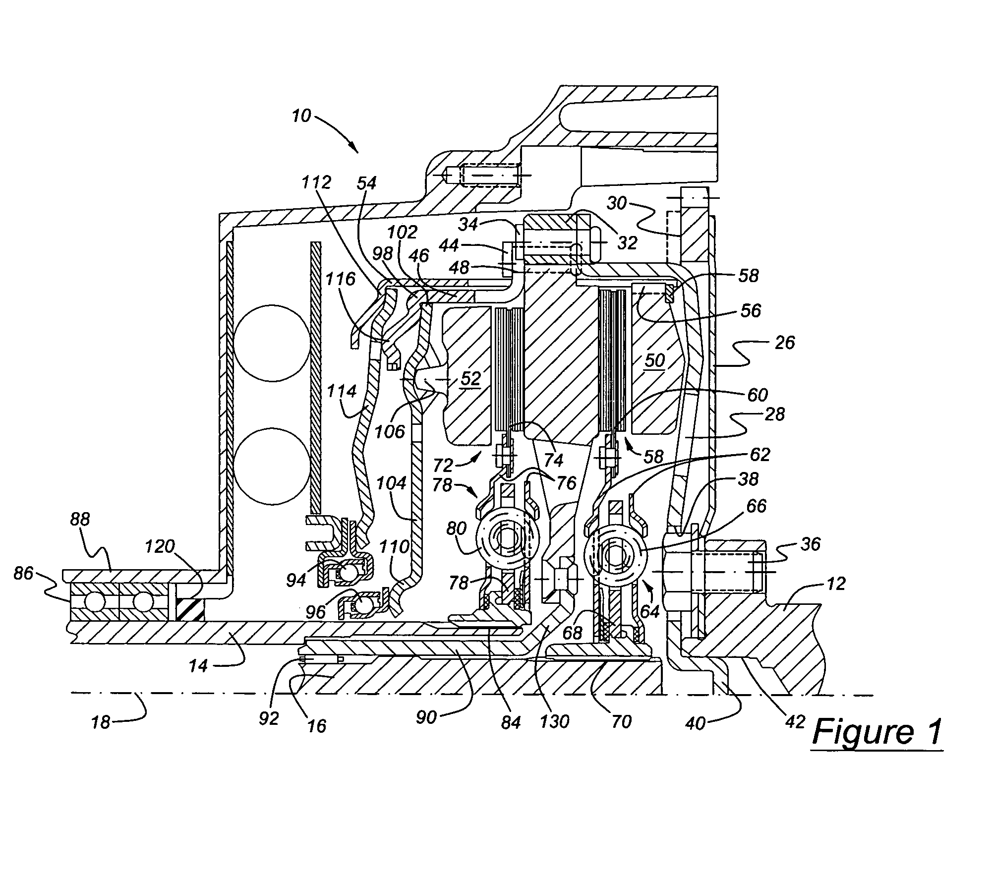
[0022]Referring now to the drawings, there is illustrated in FIG. 1 a dual clutch assembly 10 for transmitting power between an engine crankshaft 12 and first and second transmission input shafts 14, 16 alternately. Shaft 12 may be an output shaft driven by a power source such as an electric motor or hydraulic motor. Input shaft 14 may be a sleeve shaft. Input shaft 16 may be a solid shaft coaxial with shaft 12 and located within the sleeve shaft along at least a portion of its length. The transmission input shafts 14, 16 are driveably connected to gearing that produces various ratios of the speed of a transmission output shaft and the speed of the input shafts. The dual clutch assembly 10 and the input shafts are arranged about a longitudinal axis 18.

[0023]The crankshaft 12 carries a flex plate 26, a relative thin, resilient, flexible disc secured to a flywheel support disc 28 near the radial outer periphery 30 of the flex plate. A flywheel 32 is secured to the flywheel support dis...


PUM


Abstract

Apparatus for transmitting torque between a power source and a transmission, includes first and second coaxial input shafts, a housing, first bearing rotatably supporting the first input shaft on the housing, clutch assembly, flywheel, support shaft secured to the flywheel and located radially between the first and second input shafts, and second bearing located radially between the second input shaft and the support shaft. The clutch driveably connects and disconnects the flywheel and an input shaft.

Description

BACKGROUND OF THE INVENTION[0001]1. Field of the Invention[0002]The invention relates to friction clutches. In particular the invention pertains to dual friction clutches for connecting a power source output shaft alternately to input shafts of a motor vehicle transmission.[0003]2. Description of the Prior Art[0004]Conventional automotive dry clutch systems are supported directly on the engine crankshaft distant from the center of mass of the system. The mass of the clutch system is cantilevered and subject to bending displacement relative to the centerline of the crankshaft. As the crankshaft rotates, the mass of the clutch system is subject to orbiting motion about the true centerline of the crankshaft. The resulting orbiting radius from the crankshaft axis and the clutch mass together induce a first order forced vibration in the powertrain, which further increases crankshaft deflection and increases load on the system.[0005]Misalignment of the engine crankshaft centerline relativ...

Claims


Application Information

Patent Timeline
Patent Type & Authority Patents(United States)
IPC IPC(8): F16D13/58F16D21/02F16D21/06
CPCF16D21/06F16H57/0037F16D2021/0607Y10T74/19228F16H3/006F16D2021/0684
Inventor BERHAN, MICHAEL
Owner FORD GLOBAL TECH LLC
Why Eureka
Try Eureka