Eureka AIR delivers breakthrough ideas for toughest innovation challenges, trusted by R&D personnel around the world.

Cassette device for reliable filament delivery

a cassette and reliable technology, applied in the field of cassettes, can solve the problems of cassettes failing to properly deliver filament to a modeling machine, tangling or breaking, and cassettes sometimes failing to work properly

Active Publication Date: 2006-06-20
STRATSYS INC
View PDF11 Cites 70 Cited by
  • Summary
  • Abstract
  • Description
  • Claims
  • Application Information

AI Technical Summary

Benefits of technology

[0010]The present invention is an improved cassette for use in delivering a continuous length of filament, and a method of assembling the cassette. The cassette has a substantially closed housing defining a chamber in which a spool is rotatably mounted, and a path from the chamber to an exit orifice. A length of filament is wound around the spool and has a free strand which is positioned in the path. The filament strand is advanced along the path and delivered through the exit orifice by a means for advancing. To reduce filament delivery failure, a means is employed that prevents tangling of the filament in the cassette.

Problems solved by technology

This inadvertent rotation has been discovered to cause the filament to unravel, which sometimes results in tangling or breakage.
In such a case, the cassette fails to properly deliver filament to a modeling machine.
Further, even without unacceptable unwinding, it has been discovered that the cassettes sometimes fail due to imperfections in the filament wrap.
Imperfections in the wrap have been found to result in snagging of the filament as it unwinds.
This device was found to successfully prevent backward rotation but it did not prevent forward rotation.
Rather than decrease the failure rate, this resulted in increased tangling as the spool was permitted to rotate forward thereby unwinding filament, but could not likewise rotate backwards to tighten the wrap.
The foam approach was found, however, to be unsatisfactory.
While the foam did curtail rotation, it did not completely eliminate it.
Even the slightest bit of rotation of the spool during shipping was demonstrated to cause a snag within the can, and even the slightest snag was fatal.
Further, the foam caused a new set of filament delivery problems.
In some cases, the cassettes failed because the friction on the spool was too great.
Too much friction would stall out filament drive motors on the modeling machines.
The amount of friction added by the foam was difficult to control and resulted in large friction variations amongst the cassettes.
Other problems occurred as well.
Sometimes the adhesive did not hold, causing the foam to detach from the cassette and the machine to stall due to increased friction.
The foam had a tendency to crumble, and foam particles could make their way into the filament load path where they could jam or plug the modeling machine.
The foam was also difficult to apply and to remove from the cassettes.

Method used


Image

  • Cassette device for reliable filament delivery
  • Cassette device for reliable filament delivery
  • Cassette device for reliable filament delivery

Examples


embodiment one

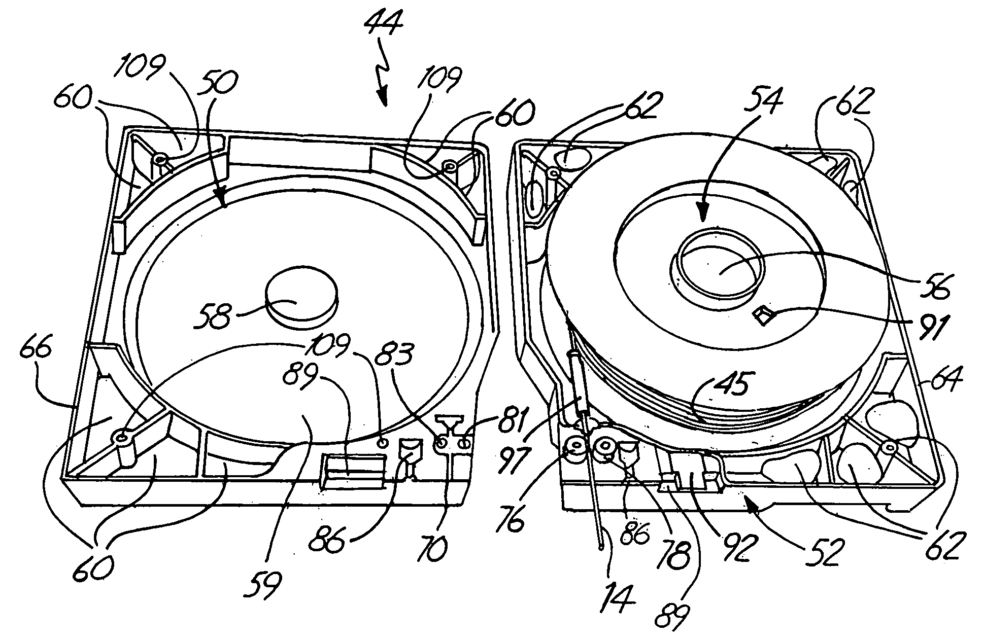
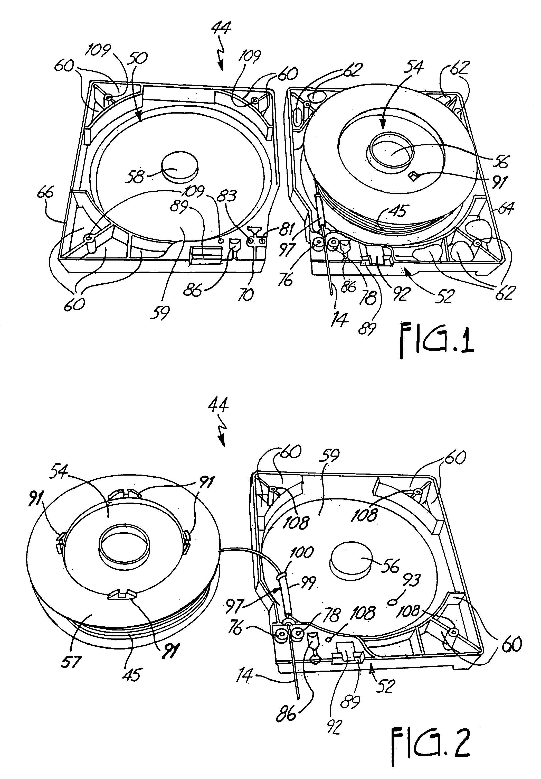
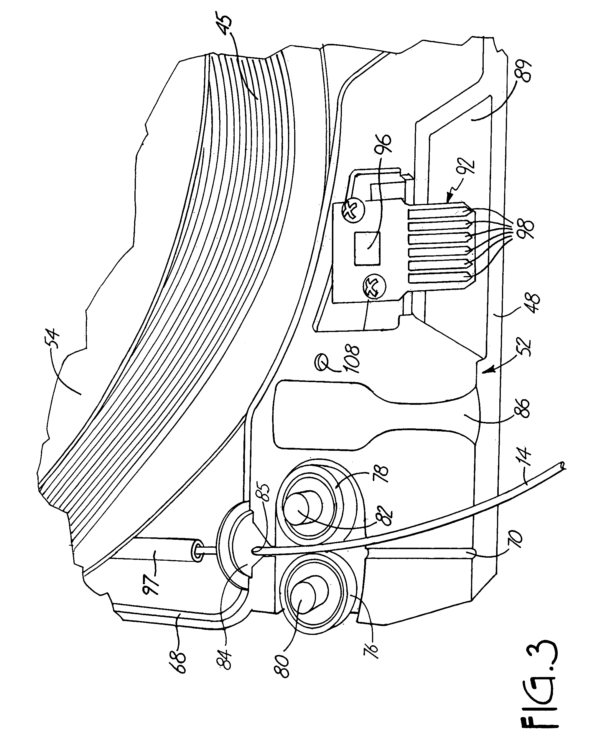
[0028]A first exemplary embodiment of the present invention is shown in FIGS. 1–5, as filament cassette 44. As shown in FIGS. 1 and 2, the filament cassette 44 is comprised of an upper shell 50, a lower shell 52, and a spool 54 carrying the filament 45. For use in three-dimensional modeling, the filament 45 is made up of a modeling material from which a three-dimensional model (or a support structure for the three-dimensional model) is to be built.

[0029]The filament 45 is wound around the spool 54 in multiple layers in any desirable manner, each layer having a plurality of windings. Typically, the windings are helical, adjacent windings traveling across the width of the spool from one side to the other, then back again. An end of the filament 45 is left unwound, providing a free strand 14.

[0030]The upper shell 50 and lower shell 52 fasten together, with the spool 54 between them. The lower shell 52 has a hub 56 and the upper shell 50 has a hub 58. A circular recess 59 within upper s...

embodiment two

[0048]FIGS. 6–10 show a second exemplary embodiment of a filament cassette 184. As shown, the filament cassette 184 is comprised of a canister 212, a guide block 214, and a spool 186. The spool 186 has two flanges 187 and carries a coil of filament 188. The canister 212 is formed of a body 216, and a lid 218 that presses onto the body 216. The interior of canister 212 defines a chamber containing the spool 186. The spool 186 rotates on a hub 220 of the body 216 and a hub 221 of the lid 218. The guide block 214 is attached to the body 216 at an outlet 224, and provides an exit path 236 terminating an exit orifice 238 for a free strand of filament 189. The guide block 214 is fastened to the canister body 216 by a set of screws (not shown) which extend through six screw holes 232 in the body 216 (shown in FIG. 7).

[0049]Like the first embodiment, the second exemplary embodiment uses the retaining pin 94 and guide member 97 to prevent tangling of filament in the cassette 184. As in the f...

embodiment three

[0060]FIGS. 11–14 show a third exemplary embodiment of the present invention, in which an alternative means for locking the spool is used in place of retaining pin 94, in a filament cassette as described in the first exemplary embodiment. In this embodiment, the spool is locked in place by a pin which secures its hub.

[0061]A hub lock 282 of the third exemplary embodiment comprises a hub-locking pin 284, a cassette hub 300, and a spool ring 298. The hub-locking pin 284 of the third exemplary embodiment has a circular base 290, a serrated edge 296 around the periphery of the base 290, a set of four receiving holes 294 extending through the base 290, and a grip 292 extending up from the base 290.

[0062]The spool ring 298 defines a hub 286 of a filament spool 288. The spool ring 298 has a serrated interior surface, which mates with the serrated edge 296 of the hub-locking pin 284. Positioning the pin 284 in the spool ring 298 engages the pin 284 with the spool 288.

[0063]In order to restr...


PUM

PropertyMeasurementUnit
Lengthaaaaaaaaaa
Adhesivityaaaaaaaaaa
Tensionaaaaaaaaaa

Abstract

A cassette for use in delivering a continuous length of filament provides improved reliability by employing means for preventing tangling of the filament in the cassette. The cassette has a substantially closed housing defining a chamber in which a spool is rotatably mounted, and a path from the chamber to an exit orifice. A length of filament is wound around the spool and has a free strand positioned in the path. The filament strand is advanced along the path and delivered through the exit orifice by a means for advancing. Tangling is prevented by locking the spool during transport of the cassette to maintain a tight wind, and by guiding the filament strand along a snag-free path as it is withdrawn from the cassette. In the exemplary embodiments, a removable pin locks a flange or hub of the spool, and the filament strand is withdrawn through a tubular guide member.

Description

CROSS-REFERENCE TO RELATED APPLICATION(S)[0001]None.BACKGROUND OF THE INVENTION[0002]This invention relates to dispensers for flexible strand materials, and particularly to cassettes that deliver modeling material in the form of a continuous filament to a machine that forms three-dimensional objects by extruding modeling material in a flowable state in three dimensions with respect to a base.[0003]Extrusion-based layered manufacturing machines build up three-dimensional objects or models by extruding solidifiable modeling material from an extrusion head in a predetermined pattern, based upon design data provided from a computer aided design (CAD) system. A feedstock of either a liquid or solid modeling material is supplied to the extrusion head. One technique is to supply modeling material in the form of a filament strand. Where the feedstock of modeling material is in solid form, a liquifier brings the feedstock to a flowable temperature for deposition. The modeling material is ext...

Claims


Application Information

Patent Timeline
IPC IPC(8): B65H16/00
CPCB65H49/322B29C67/0055B29C64/106B29C64/118
Inventor TURLEY, PATRICK W.TAATJES, THOMAS L.
Owner STRATSYS INC
Why Eureka
Eureka Blog
Learn More