Conveyor system

a conveying system and conveying technology, applied in the field of conveying systems, can solve the problems of easy fracture of conveying wires or other problems, and achieve the effect of safe conveyancing and easy positioning of workpieces

Inactive Publication Date: 2006-06-20
SHINKO ELECTRIC IND CO LTD
View PDF4 Cites 13 Cited by
  • Summary
  • Abstract
  • Description
  • Claims
  • Application Information

AI Technical Summary

Benefits of technology

[0008]An object of the present invention is to provide a conveyor system enabling safe conveyance and easy positioning of a workpiece without damaging a thin workpiece of a thickness of less than 100 μm.
[0009]The inventors studied how to achieve this object and as a result discovered that by using a movable plate-shaped member formed with a plurality of Bernoulli nozzles and a plurality of vacuum chucking nozzles alternately at the workpiece chucking surface near the outer periphery of the plate-shaped member along the outer periphery, it is possible to safely convey a thin workpiece having a thickness of less than 100 μm and easily position the workpiece without damaging it and thereby perfected the present invention.
[0011]By comprising the holding means by a plurality of vacuum chucking nozzles and by alternately forming the plurality of Bernoulli nozzles forming the lifting means and the plurality of vacuum chucking nozzles on the workpiece chucking surface near the outer periphery of the plate-shaped member along the outer periphery, it is possible to simplify the structure of the plate-shaped member. By using a porous member for a chucking pad of a vacuum chucking nozzle, it is possible to eliminate the danger of making chucking marks on the workpiece. Further, by comprising the holding means by at least one electrostatic chucking plate and providing the electrostatic chucking plate at the workpiece chucking surface of the plate-shaped member, it is possible to further simplify the structure of the plate-shaped member for an electrostatically chuckable workpiece. In the present invention, since a lifting means and a holding means are both used, by providing a controller for controlling a drive timing of the two, it is possible to accurately drive and stop the two means at predetermined timings and possible to reliably convey the workpieces. Further, by providing a detachment prevention member for preventing part of the workpiece lifted by the plurality of Bernoulli nozzles from being detached from the plate-shaped member at the outer periphery of the plate-shaped member, it is possible to reliably position the workpiece at one surface of the plate-shaped member. By biasing the detachment prevention member by an elastic member in a direction where its front end projects out from the workpiece chucking surface of the plate-shaped member, it is possible to easily change the length of the detachment prevention member projecting out from the workpiece chucking surface of the plate-shaped member by adjusting the biasing force of the elastic member etc. Further, by providing a switching station provided with a plurality of pressurized air blowing nozzles blowing pressurized air from below the workpiece so as to prevent the workpiece from dropping off when switching a workpiece lifted by the lifting means comprised of a plurality of Bernoulli nozzles to holding by the holding means, it is possible to reliably prevent a situation where the workpiece drops off and is damaged when switching from the lifting means to the holding means.
[0012]According to the present invention, it is possible to equally lift a workpiece having a thickness of less than 100 μm carried at the carrying location without the workpiece as a whole abutting against the workpiece chucking surface of the plate-shaped member by a plurality of Bernoulli nozzles formed in the workpiece chucking surface near the outer periphery of the plate-shaped member along the outer periphery. Further, the lifted workpiece is held by chucking to the workpiece chucking surface of the plate-shaped member equally as a whole by a holding means provided at the plate-shaped member. In this way, it is possible to easily recognize the position of a workpiece chucked to the workpiece chucking surface of the plate-shaped member and possible to position the workpiece by moving and / or swiveling the plate-shaped member by a moving and swiveling means based on this recognition.
[0013]According to a second aspect of the present invention, there is provided a conveyance method using any of the above conveyor systems including the steps of moving the plate-shaped member to a first position on which a workpiece is placed, lowering the plate-shaped member down to the workpiece, starting the blowing of air from the Bernoulli nozzles, chucking the workpiece by the Bernoulli nozzles, lifting up the plate-shaped member, starting suction by vacuum chucking nozzles to chuck the workpiece by both of the vacuum chucking nozzles and Bernoulli nozzles, stopping the blowing of air from the Bernoulli nozzles and chucking the workpiece by only the vacuum chucking nozzles, and moving the plate-shaped member to a second position for processing of the next workpiece.

Problems solved by technology

If conveying such thin wafers using the conveyor system shown in FIGS. 9A and 98, it is learned that the wafers will easily fracture or other problems will occur during conveyance.

Method used


Image

  • Conveyor system
  • Conveyor system
  • Conveyor system

Examples


Embodiment Construction

[0023]Preferred embodiments of the present invention will be described in detail below while referring to the attached figures.

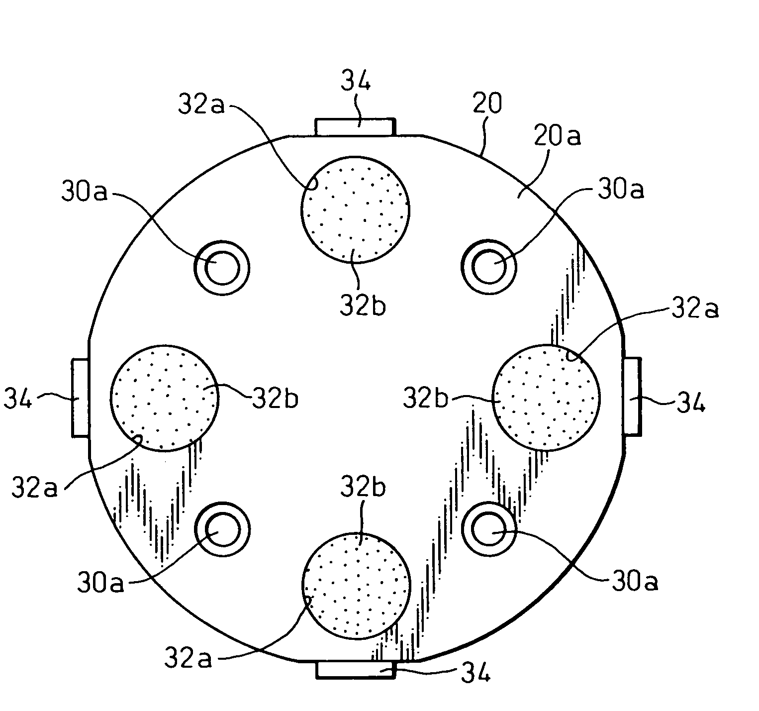
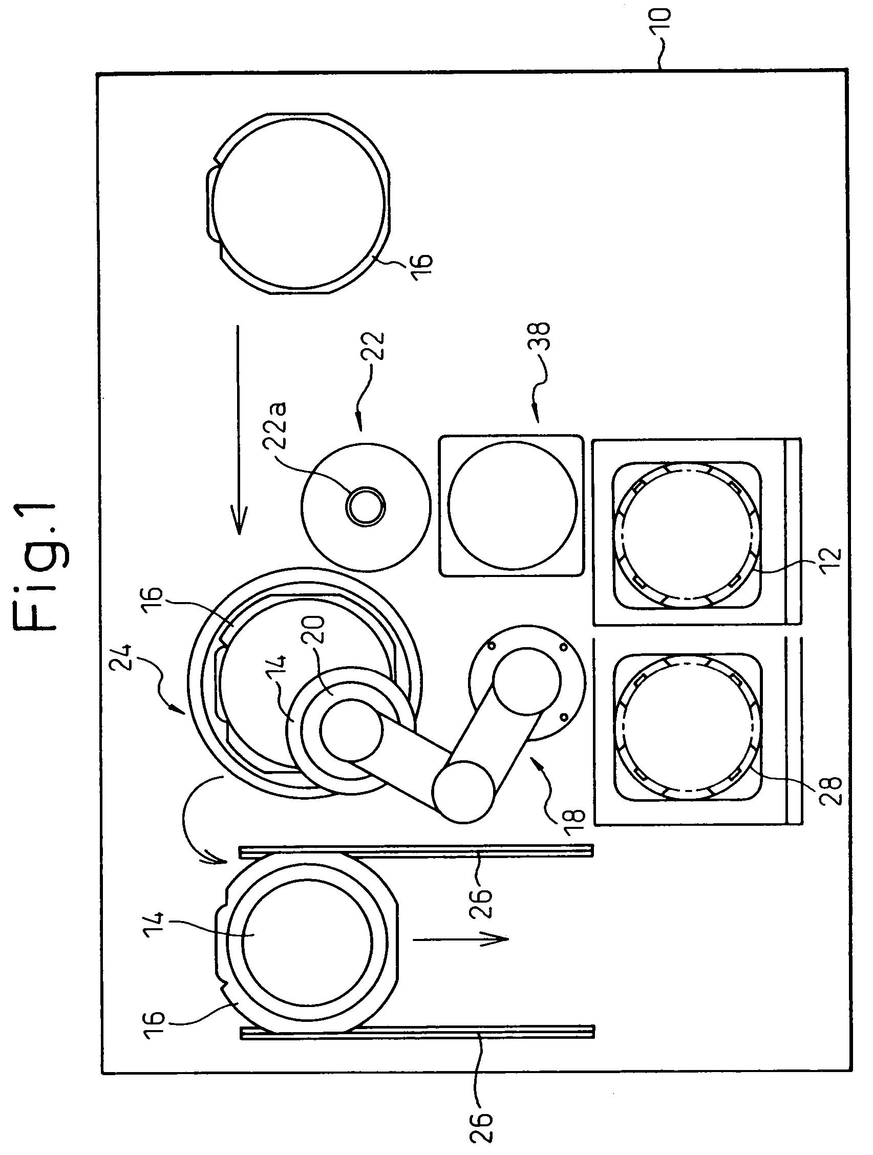
[0024]FIG. 1 shows a conveyor system taking out from a cassette 12 placed at a carrying position of a base 10 a silicon wafer 14 having a thickness of less than 100 μm as one of a plurality of workpieces stacked via interlayer paper (hereinafter referred to simply as a “wafer 14” in some cases) in the cassette 12, positioning it, and adhering it to an adhesive ring 16. In the conveyor system shown in FIG. 1, a multiarticulated robot 18 is placed on the base 10. Around this, a position measurement area 22 on which a camera 22a is provided, an adhesion area 24 for adhering a wafer 14 positioned by the tape adhered to the adhesive ring 16, and rails 26, 26 for sending to the next step the adhesive ring 16 on which a wafer 14 is attached by the tape.

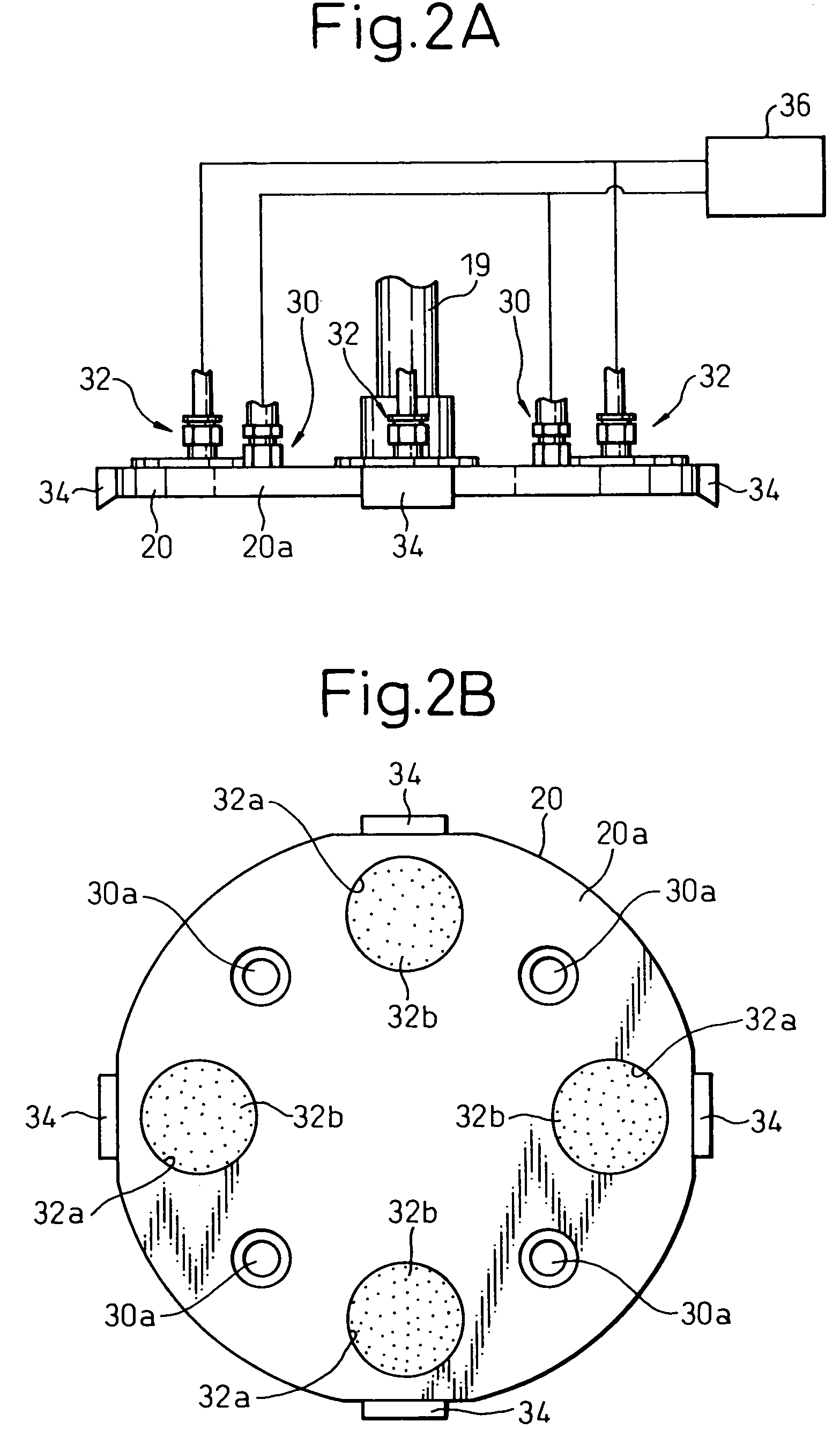
[0025]The front end head of the multiarticulated robot 18 has the plate-shaped member 20 attached swivelably to it...


PUM


Abstract

A conveyor system able to safety convey a workpiece having a thickness of less than 100 μm and easily position the workpiece, provided with a plate-shaped member provided movably and swivelably and a moving and swiveling means moving and swiveling the plate-shaped member, the plate-shaped member being provided together with a lifting means for uniformly lifting in its entirety a workpiece carried at the carrying location and a holding means for holding a workpiece lifted by the lifting means by chucking its entirety on a workpiece chucking surface of the plate-shaped member, and a plurality of Verneuil nozzles serving as the lifting means and a plurality of vacuum chucking nozzles serving as the holding means being formed in the workpiece chucking surface near an outer periphery of the plate-shaped member along the outer periphery.

Description

BACKGROUND OF THE INVENTION[0001]1. Field of the Invention[0002]The present invention relates to a conveyor system, more particularly relates to a conveyor system for conveying a wafer or other thin workpiece having a thickness of not more than 100 μm from a carrying location to another location.[0003]2. Description of the Related Art[0004]When conveying a wafer or other thin workpiece from a carrying location to another location, use can be made of a conveyor system as disclosed in for example U.S. Pat. No. 4,566,726, in particular FIG. 2A and FIG. 2B.[0005]The conveyor system disclosed in this is shown in FIGS. 9A and 9B. The conveyor system is a conveyor system for conveying a wafer or other workpiece 100 provided with a plate-shaped member 102 at the center of one surface 102a where a Bernoulli nozzle 104 is formed. This Bernoulli nozzle 104 has a baffle plate 104a at its nozzle part and a pressurized air blowing port 104b formed in a crescent shape. Therefore, the pressurized a...

Claims


Application Information

Patent Timeline
Patent Type & Authority Patents(United States)
IPC IPC(8): B25J15/00B25J15/06B65G49/07H01L21/677H01L21/683
CPCH01L21/6838
Inventor MIYAMOTO, AKIHIRO
Owner SHINKO ELECTRIC IND CO LTD
Why Eureka
Try Eureka