Pump for liquid chromatography

a liquid chromatography and pump technology, applied in the field of pump for liquid chromatography, can solve the problems of reducing the speed of the motor to reduce the speed of the plunger, the diameter or the stroke of the plunger is decreased, and the liquid cannot be fed at a large flow ra

Inactive Publication Date: 2006-06-20
HITACHI HIGH-TECH CORP
View PDF20 Cites 67 Cited by
  • Summary
  • Abstract
  • Description
  • Claims
  • Application Information

AI Technical Summary

Problems solved by technology

However, in the above-described conventional pump for liquid chromatography, in a case where in order to feed liquid at a low flow rate, the speed reduction ratio of a motor is increased to decrease the speed of the plunger or the diameter or stroke of the plunger is decreased, conversely, the liquid can not be fed at a large flow rate.
For this reason, this pump presents a problem that it takes much time to fill solvent into the passage of a measurement system on the downstream side of the pump at the startup of test and a problem that bubbles remaining in the pump can not be easily discharged.
Therefore, there is presented a problem that this pump is not appropriate for constructing a pump used for an extremely low flow rate.
However, even if the check valve of this kind is closed, minute leakage cannot be avoided and in particular, in the case of feeding liquid at an extremely low flow, becomes a large factor to reduce a liquid feed accuracy.
On the other hand, the check valve constructed of a soft material such as resin has high hermeticity and hence can minimize leakage but is not applicable because of durability.
In this manner, there is presented a problem that the check valve cannot feed liquid at an extremely low flow rate with high accuracy.

Method used


Image

  • Pump for liquid chromatography
  • Pump for liquid chromatography
  • Pump for liquid chromatography

Examples


Embodiment Construction

[0028]The embodiments in accordance with the invention will be described with reference to the drawings.

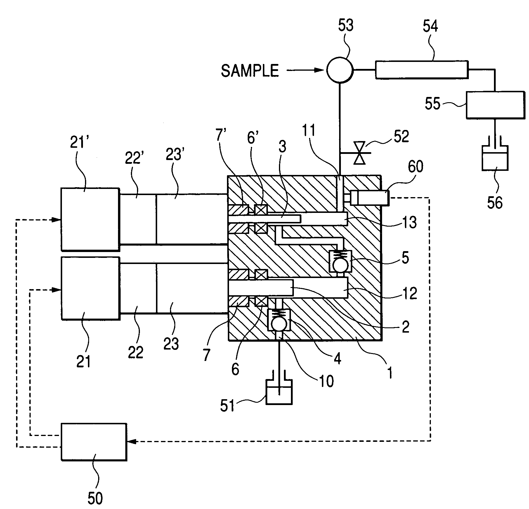
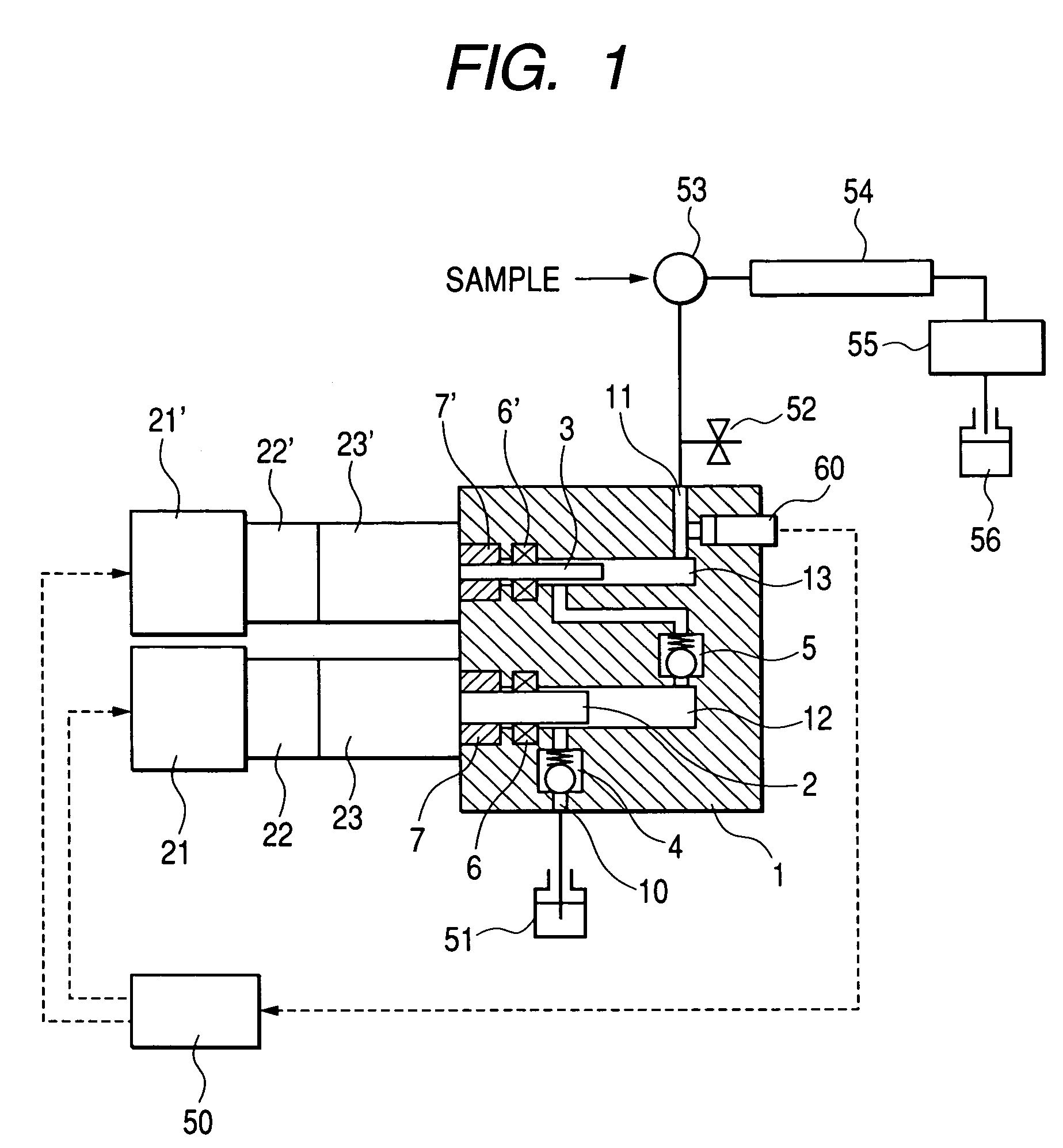
[0029]The construction and operation of one embodiment in accordance with the invention will be described by use of FIG. 1 to FIG. 3. In FIG. 1, in a pump body 1 are formed a suction passage 10, a discharge passage 11, a first pressure chamber 12, and a second pressure chamber 13. In the first pressure chamber 12 and the second pressure chamber 13, a first plunger 2 and a second plunger 3 that are members for applying pressure, respectively, are slidably held by bearings 7, 7′. The suction passage 10 is provided with a suction check valve 4 and a middle passage that makes the first pressure chamber 12 communicate with the second pressure chamber 13 is provided with a discharge check valve 5. Each of the suction check valve 4 and the discharge check valve 5 is held in one direction by a spring and becomes a check valve to limit the direction in which solvent flows. The rotation of ...


PUM

PropertyMeasurementUnit
flow rateaaaaaaaaaa
flow rateaaaaaaaaaa
pressureaaaaaaaaaa

Abstract

The invention provides a pump for liquid chromatography excellent in feeding liquid stably at an extremely low flow rate with high accuracy and in discharging bubbles at startup.At startup, a first plunger feeds solvent at a large flow rate to discharge bubbles in a pump and to fill the solvent into the pump in a short time and in a normal operation, the first plunger is stopped and the second plunger is pushed into a second pressure chamber at a low speed to feed the solvent at a low flow rate. When the second plunger reaches full stroke, the second plunger is pulled back at a high speed and at the same time the first plunger is pushed into a first pressure chamber in synchronization with the pullback of the second plunger to control the flow rate passing a discharge passage to a constant value at all times by a controller. Further, while the second plunger feeds the solvent, the first plunger is slightly pushed into the first pressure chamber to keep pressure in the first pressure chamber at pressure equal to or less than pressure in the second pressure chamber.

Description

CLAIM OF PRIORITY[0001]The present application claims priority from Japanese application serial JP 2003-205234 filed on Aug. 1, 2003, the content of which is hereby incorporated by reference into this application.FIELD OF THE INVENTION[0002]The present invention relates to liquid chromatography and in particular, to a pump for liquid chromatography that is excellent in feeding liquid stably at a low flow rate.BACKGROUND OF THE INVENTION[0003]As a conventional pump for liquid chromatography has been known a construction in which a first plunger and a second plunger are driven independently and cooperatively by motors to reduce a pulsating flow rate (for example, see patent document 1).[0004]Describing this construction, while the first plunger reciprocates one time, the second plunger also reciprocates one time to correct a pulsating flow rate caused by the suction of the first plunger by the operation of the second plunger. That is, in this construction, the first plunger determines...

Claims


Application Information

Patent Timeline
Patent Type & Authority Patents(United States)
IPC IPC(8): B01D15/08B01D15/14F04B1/02G01N30/32F04B11/00F04B13/02F04B23/06F04B53/06
CPCF04B11/0058F04B11/0083F04B53/06F04B13/02B01D15/14G01N2030/326F04B2205/09
Inventor HIRAKU, KENJITAKAO, KUNIHIKOKAJI, HIRONORIITO, MASAHITO
Owner HITACHI HIGH-TECH CORP
Why Eureka
Try Eureka