
Method and apparatus for receiving video signals from a plurality of video cameras

a video camera and video signal technology, applied in the field of video signal reception from a plurality of video cameras, can solve the problems of time-consuming process of conditioning the video decoder, unacceptably long time required for the system b>100/b> to perform a complete cycle of all the cameras, and achieve the effect of less time, less time, and duplicate storage locations for storing parameters

Inactive Publication Date: 2006-06-20
SEMICON COMPONENTS IND LLC
View PDF13 Cites 35 Cited by
  • Summary
  • Abstract
  • Description
  • Claims
  • Application Information

AI Technical Summary

Benefits of technology

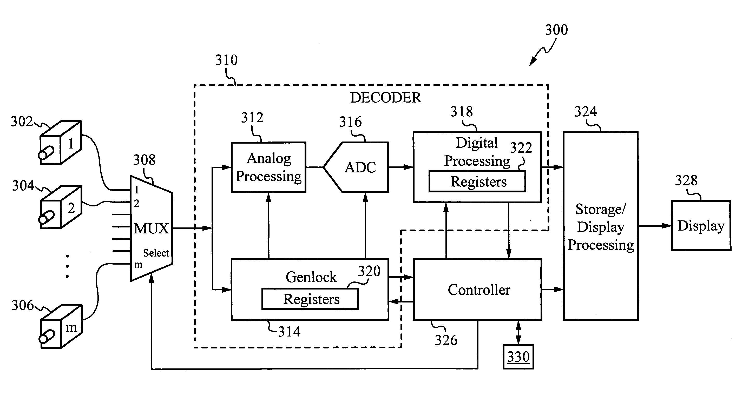
[0016]Therefore, the invention duplicates storage locations for storing parameters corresponding to each camera, rather than requiring multiple video decoders, as in prior systems. As a result of storing parameters corresponding to each camera and utilizing these parameters to initialize the video decoder, the amount of time required by the present invention to condition the video decoder is significantly reduced in comparison to prior systems using a single decoder. Accordingly, the present invention allows a surveillance system to cycle through each of a plurality of cameras in less time than prior systems having a single video decoder, but without the high cost associated with prior systems which employ multiple video decoders.

Problems solved by technology

Because each of these steps must be performed before the next, this process of conditioning the video decoder is time consuming.
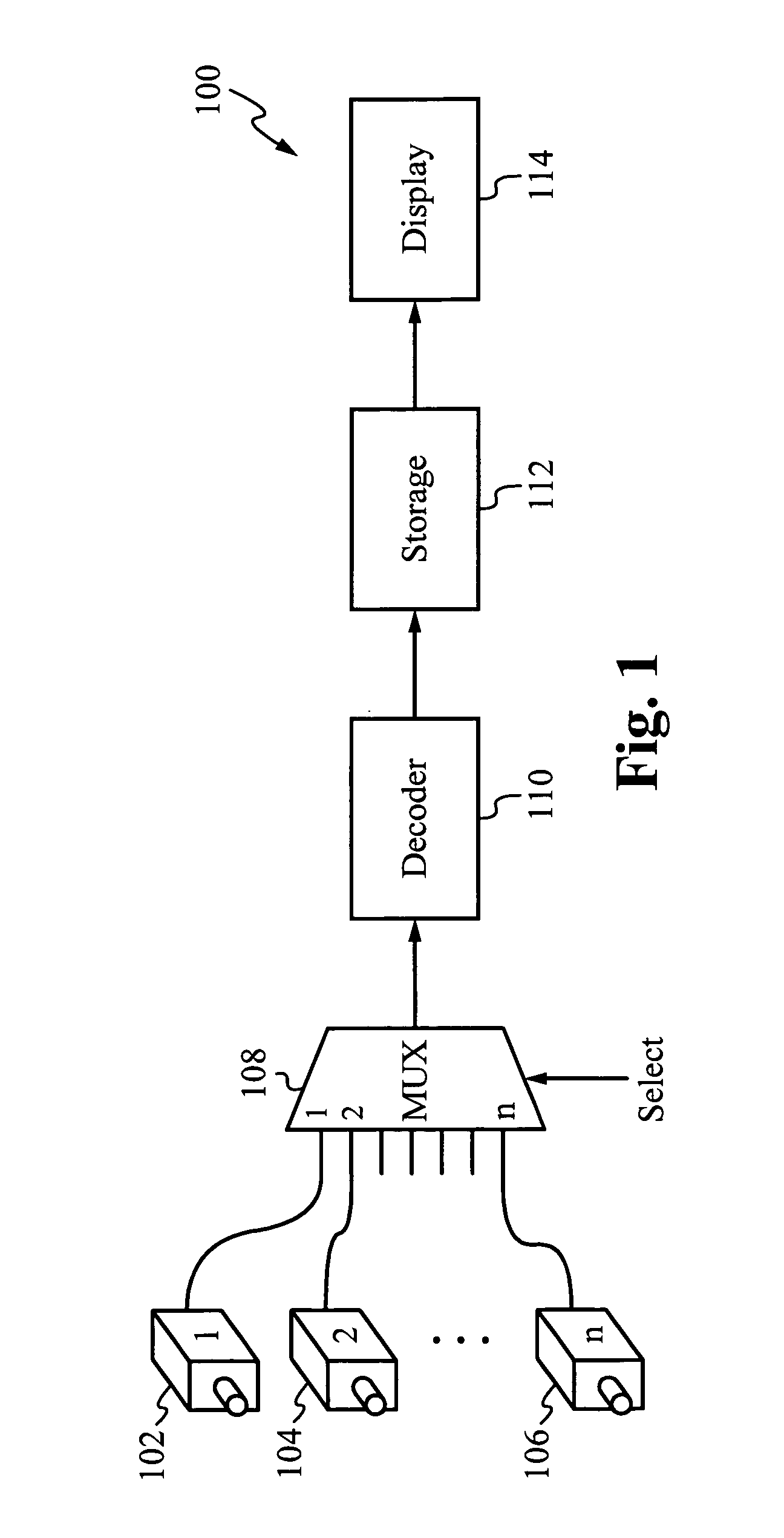
A drawback to the surveillance system 100 illustrated in FIG. 1 is that because a finite amount of time is required to re-condition the decoder 110 each time the multiplexer 108 selects a video signal from a different one of the cameras 102–106 in the sequence, the speed at which the system 100 can scan from one camera to the next is limited.
As the number of cameras is increased, however, the time required for the system 100 to perform a complete cycle of all the cameras can become unacceptably long.
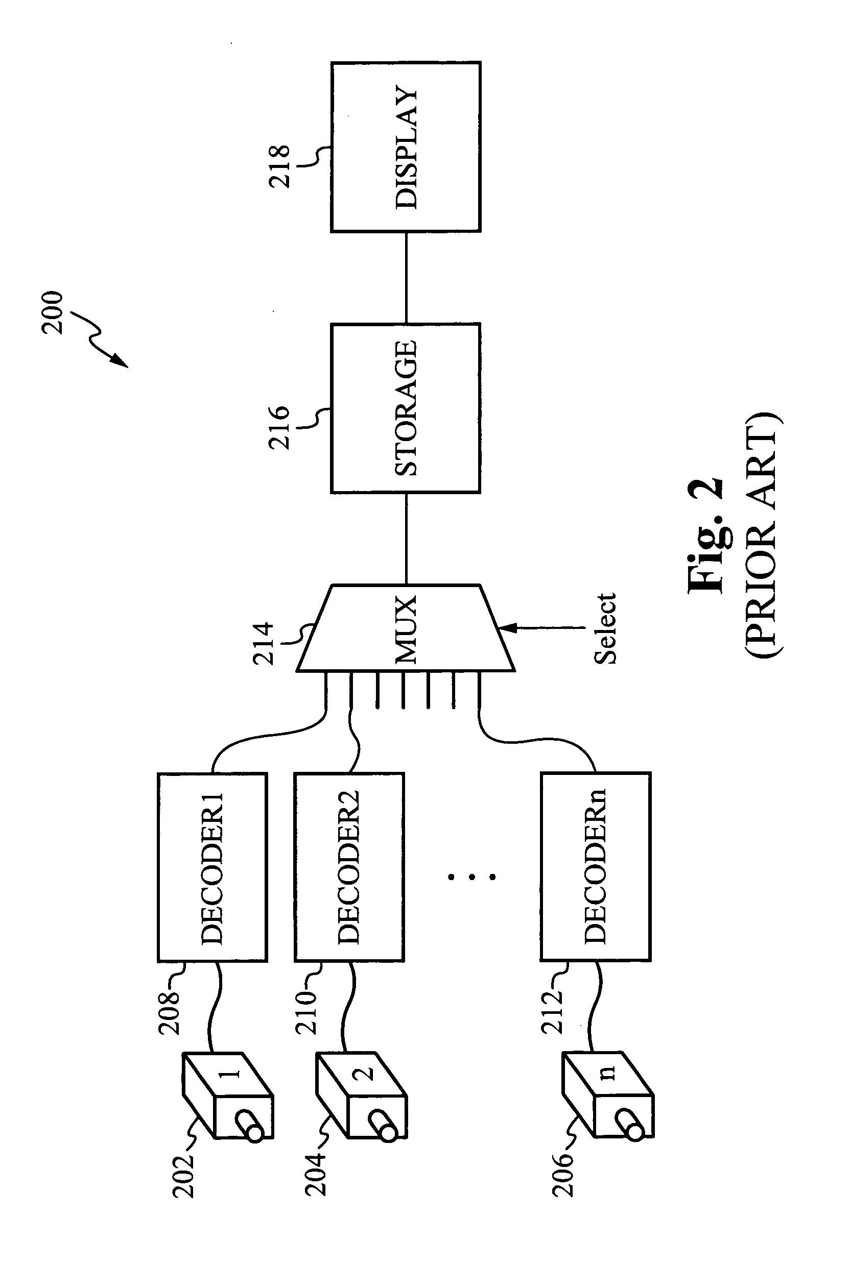
Further, as the number of cameras increases, this cost difference also increases.
Therefore, prior video surveillance systems exhibit a trade-off in that increases in performance are accompanied by significant increases in cost.

Method used


Image

  • Method and apparatus for receiving video signals from a plurality of video cameras
  • Method and apparatus for receiving video signals from a plurality of video cameras
  • Method and apparatus for receiving video signals from a plurality of video cameras

Examples


Embodiment Construction

[0021]FIG. 3 illustrates a schematic block diagram of a video surveillance system 300 in accordance with a preferred embodiment of the present invention. A plurality of (m) video cameras 302, 304 and 306 are positioned at various locations and are each coupled to provide a video signal to a respective input of a multiplexer 308. A select input of the multiplexer 308 conditions the multiplexer 308 to route a selected one of the video signals from the cameras 302–306 to an output of the multiplexer 308. The cameras 302–306 need not be synchronized to each other. Accordingly, video signals formed by the cameras 302–306 can vary from each other in frequency, phase, amplitude and dc offset.

[0022]An output of the multiplexer 308 is coupled to a video decoder 310. The video decoder 310 includes an analog processing block 312, a genlock block 314, an analog-to-digital converter (ADC) 316, and a digital processing block 318. The selected video signal from the output of multiplexer 308 is pro...


PUM


Abstract

A method and apparatus for receiving video signals from a plurality of video cameras, such as in a video surveillance system. The video cameras are each coupled to provide a video signal to a respective input of a multiplexer. The multiplexer routes a selected one of the video signals to a video decoder. The video decoder receives the selected video signal and is conditioned according to the video signal. This includes synchronizing the video decoder to a frequency and phase of the video signal, controlling a gain level for the video signal and adjusting a dc clamping level for dc restoration of the video signal. Parameters representative of each of these quantities are stored in association with the identity of the corresponding video camera. The video decoder also places each video signal into a format suitable for storage in a storage device and for display by a display device. As the multiplexer is utilized to cycle through the cameras according to a sequence, the parameters for each camera are retrieved and utilized to initialize the video decoder for decoding the video signal received from the corresponding camera. As a result, the amount of time required to condition the video decoder according to the video signal received from each camera is significantly reduced. Accordingly, the present invention allows a surveillance system to cycle through a plurality of cameras in less time than prior systems having a single decoder, but without higher costs associated with prior systems which employ multiple video decoders.

Description

FIELD OF THE INVENTION[0001]The present invention relates to the field of receiving video signals from a plurality of video cameras. More particularly, the present invention relates to the field of rapidly synchronizing an apparatus for sequentially receiving video signals from each of a plurality of video cameras.BACKGROUND OF THE INVENTION[0002]A video camera typically forms an analog composite video signal which is representative of a moving optical image received by the camera. To form the video signal, a sensing spot moves across an image area according to a series of horizontal scan lines arranged from the top of the image area to the bottom of the image area. A complete scan of the image area represented by the video signal is referred to as a “frame.” When the bottom of the image area is reached, the process begins again at the top thereby forming a series of frames. National Television Standards Committee (NTSC) and Phase Alternate Line (PAL) are two widely utilized standar...

Claims


Application Information

Patent Timeline
Patent Type & Authority Patents(United States)
IPC IPC(8): H04B1/66
CPCH04N7/181
Inventor RITTER, DAVID W.BICAKCI, ARA
Owner SEMICON COMPONENTS IND LLC
Learn More