
Automatic generation of flow control frames

a flow control and automatic generation technology, applied in the field of data communication, can solve problems such as the suspension of transmission of the transmitting devi

Inactive Publication Date: 2006-06-20
ADVANCED MICRO DEVICES INC
View PDF20 Cites 25 Cited by
  • Summary
  • Abstract
  • Description
  • Claims
  • Application Information

AI Technical Summary

Benefits of technology

[0006]The present invention offers a novel system for performing automatic flow control in a computer system that comprises a local bus, a host processor coupled to the local bu...

Problems solved by technology

The collision causes the transmitting device to suspend its transmission for a random amount of time.

Method used


Image

  • Automatic generation of flow control frames
  • Automatic generation of flow control frames
  • Automatic generation of flow control frames

Examples


Embodiment Construction

[0021]Although the invention has general applicability in the field of data processing, the best mode for practicing the invention is based in part on the realization of a network interface in a packet switched network, such as an Ethernet (IEEE 802.3) network.

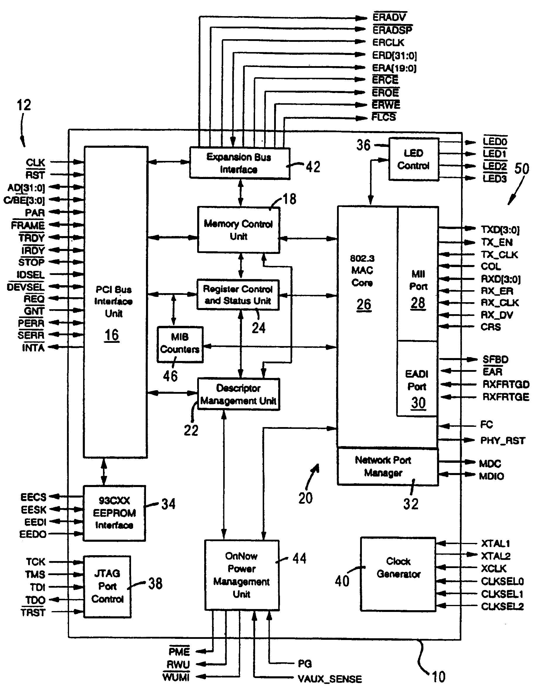
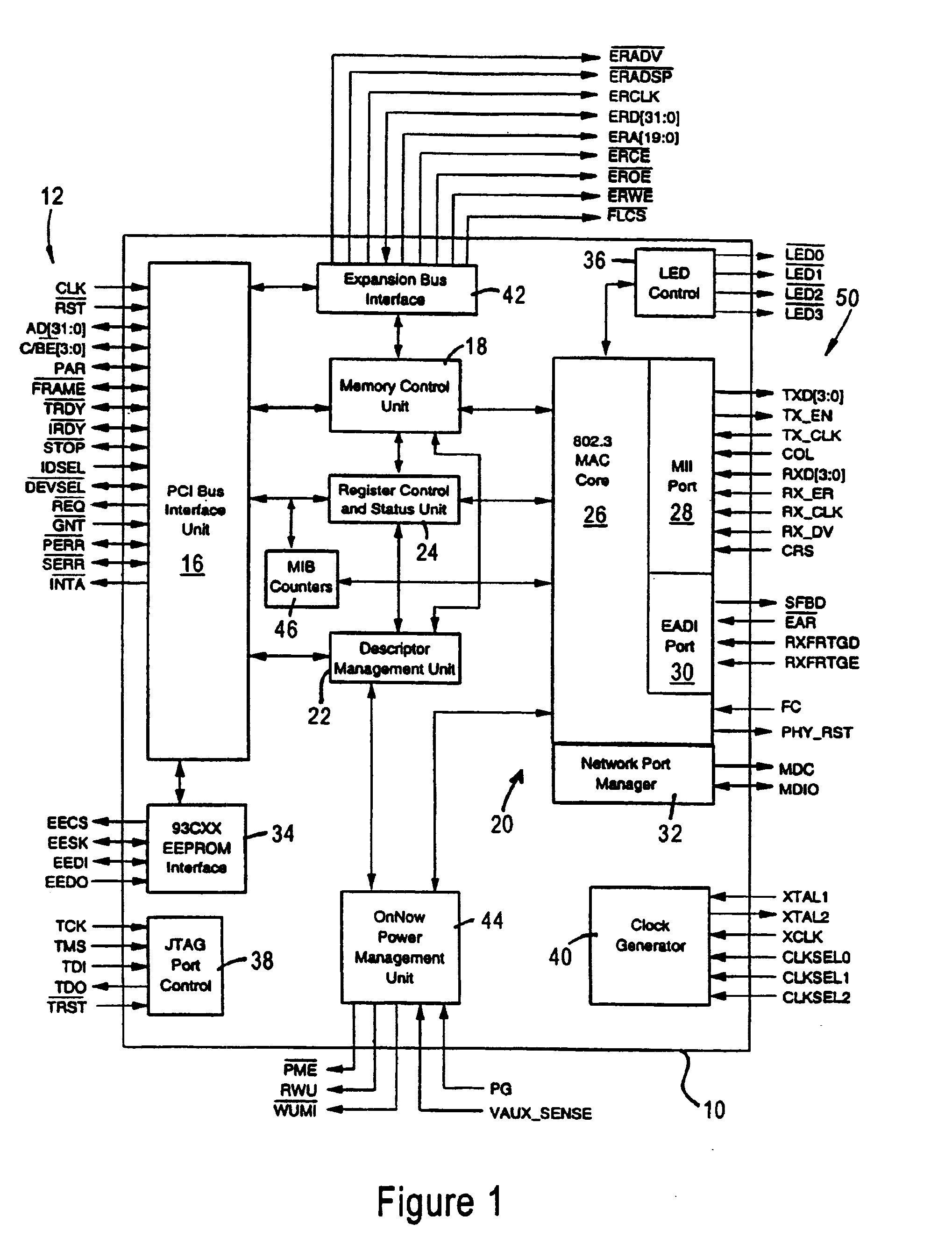
[0022]FIG. 1 is a block diagram of an exemplary network interface 10 that accesses the media of an Ethernet network according to an embodiment of the present invention.

[0023]The network interface 10, preferably a single-chip, 32-bit Ethernet controller, provides an interface between a local bus 12 of a computer system, for example, a peripheral component interconnect (PCI) local bus, and an Ethernet-based media 50. The reference numeral 50 identifies either an actual network medium, or alternately a signal path (e.g., a media independent interface (MII)) to a physical layer transceiver coupled to the network media. The computer system is controlled by a host CPU coupled to the bus 12.

[0024]The network interface 10 includes a P...


PUM


Abstract

An automatic flow control mechanism that supports two modes of automatic flow control is provided in a network interface. In the first flow control mode, the network interface periodically compares the number of available receive descriptors with low and high threshold values. When the number of available receive descriptors falls below the low threshold value, the network interface sends a PAUSE frame requesting the link partner to suspend its transmission (in a full-duplex mode), or enables the back pressure mechanism (in a half-duplex mode). In the second flow control mode, when the network interface detects that the number of available receive descriptors is less than the low threshold value, it transmits a PAUSE frame requesting the link partner to suspend its transmission for a time period corresponding to a preprogrammed pause value (in a full-duplex mode), or enables the back pressure mechanism, at least, for a time interval defined by a pause timer loaded with the preprogrammed pause value (in a half-duplex mode).

Description

[0001]This patent application claims priority of U.S. provisional patent application No. 60 / 171,300 entitled “AUTOMATIC FLOW CONTROL IN NETWORK INTERFACE DEVICE”, filed on Dec. 21, 1999.FIELD OF THE INVENTION[0002]The present invention relates to data communications, and more particularly, to a network interface device having an automatic flow control mechanism.BACKGROUND ART[0003]A flow control mechanism is provided in a data network for controlling the transfer of data between network devices so as to prevent loss of data when the receiving device is not able to accept new messages or characters. For example, the Ethernet protocol (IEEE Std. 802.3, Annex 31B) defines a mechanism that allows a Media Access Control (MAC) device operating in a full-duplex mode to request that its link partner stop transmitting for a specified period of time. In particular, the MAC device transmits a MAC control PAUSE frame that specifies the length of time for which the link partner should suspend it...

Claims


Application Information

Patent Timeline
IPC IPC(8): G06F15/16G06F13/00
CPCG06F13/387H04L47/29H04L47/263H04L47/10
Inventor DWORK, JEFFREYWILLIAMS, ROBERT ALAN
Owner ADVANCED MICRO DEVICES INC
Features
  • Generate Ideas
  • Intellectual Property
  • Life Sciences
  • Materials
  • Tech Scout
  • Unparalleled Data Quality
  • Higher Quality Content
  • 60% Fewer Hallucinations
Learn More