Interface module for transmitting digital video signal

a technology of interface modules and digital video signals, applied in the field of interface modules, can solve the problems of increasing size and cost, inability to achieve, and disadvantageous in terms of user-friendliness of interface modules

Inactive Publication Date: 2006-06-20
SUMITOMO ELECTRIC IND LTD
View PDF6 Cites 56 Cited by
  • Summary
  • Abstract
  • Description
  • Claims
  • Application Information

AI Technical Summary

Benefits of technology

[0028]Thus, the present invention having the above-described structure makes it possible to achieve the long-distance transmission of video signals.

Problems solved by technology

As a result, with this interface module, the identification of the video output display unit 2 cannot be achieved, and the display type and synchronization frequency must be set manually with the host device 1, which is burdensome.
This may result in an increase in size and cost.
This imposes restrictions with respect to the position at which the interface module can be placed, which is disadvantageous in terms of user-friendliness of the interface module.
The larger the number of optical fibers, the larger the space required, and hence the module becomes less user-friendly.
This causes transmission errors, and the video output display unit cannot be accurately identified.
Since different treatments of the termination must be performed, the termination work requires time, the structure of the connector becomes complicated, and the cost for the termination is increased.
Also, since the cable size increases, a larger space is necessary for connecting the host device and the display unit.
Furthermore, since the composite cable has a complicated structure and requires a lot of time for termination work, the structure of a connector thereof becomes complicated and the cost is increased in a case where a extension cable is to be connected for extending the composite cable, for example.

Method used


Image

  • Interface module for transmitting digital video signal
  • Interface module for transmitting digital video signal
  • Interface module for transmitting digital video signal

Examples


Embodiment Construction

[0038]With reference to the accompanying drawings, embodiments of the present invention will now be described. The same reference numerals are used to refer to the same components, and repeated descriptions of common portions are omitted. The scale of the drawings does not necessarily agree with that of the description.

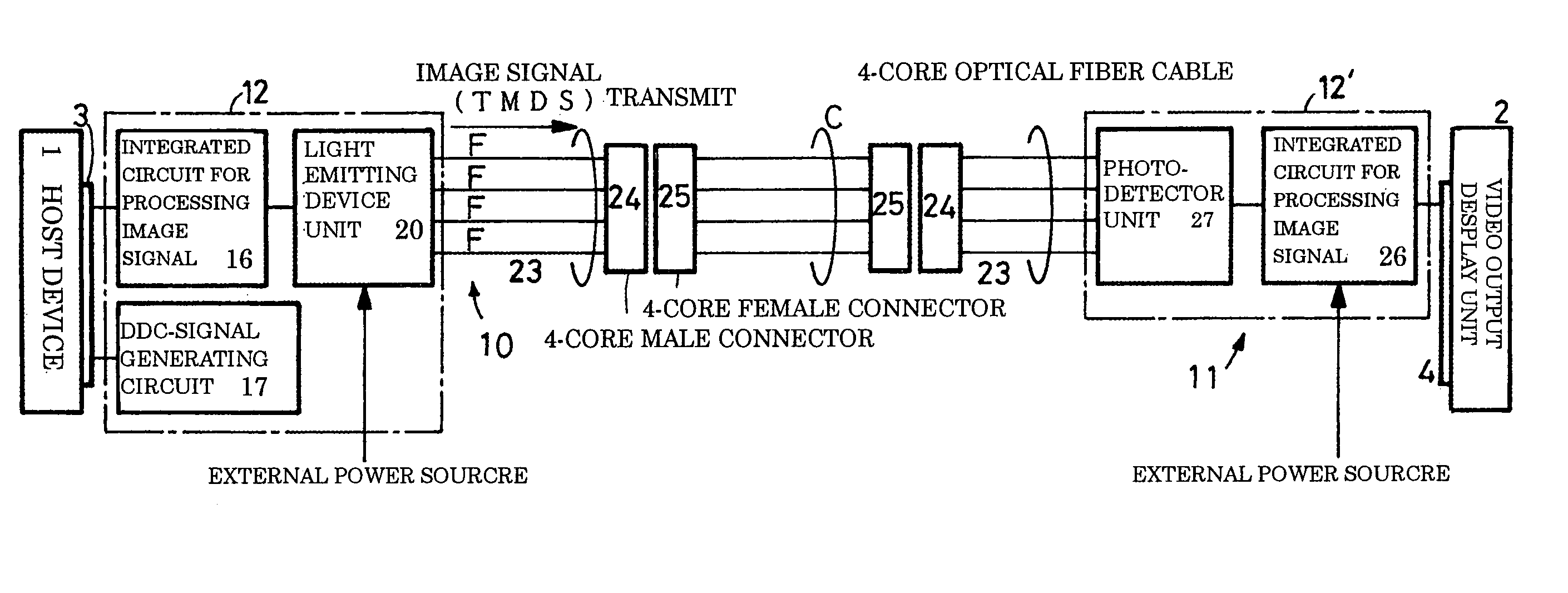
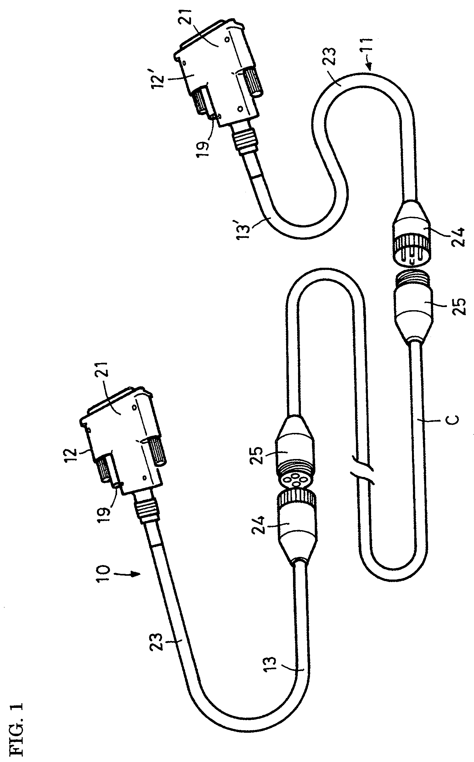
[0039]Referring to FIG. 1, an interface module for transmitting a digital video signal of this embodiment includes a transmitting interface unit 10, a receiving interface unit 11, and an optical cable unit C connecting these interface units 10 and 11.

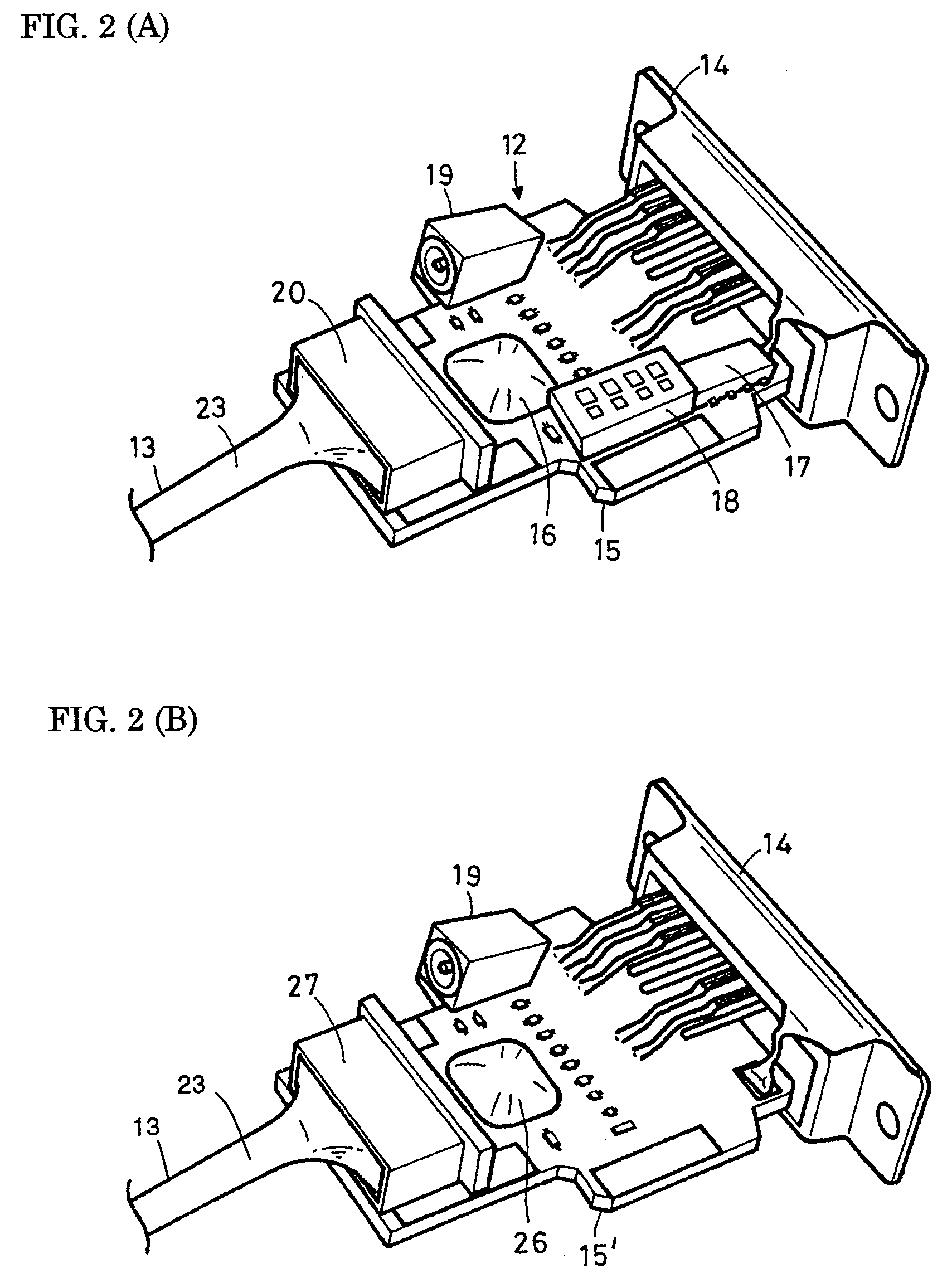
[0040]The transmitting interface unit 10 includes a connector 12 and a cable connection 13. Referring to FIG. 2A, the connector 12 has a structure such that integrated circuits 16 and 17, a selector switch 18, an external power terminal 19, and a light emitting device unit 20 are disposed on a circuit board 15 provided with a DVI connector 14, and the connector 12 is enclosed in a resin cover 21 as shown in FIG. 1. The li...


PUM

PropertyMeasurementUnit
lengthsaaaaaaaaaa
thicknessaaaaaaaaaa
sizeaaaaaaaaaa

Abstract

An interface module for transmitting a digital video signal includes: a transmitting interface unit which is designed to be connected to a host device for outputting a video signal, and which has a cable connection consisting of a 4-core optical fiber cable and a 4-core male connector provided at one end thereof; a receiving interface unit having a cable connection designed to be connected to a video output display unit and consisting of a 4-core optical fiber cable and a 4-core male connector provided at one end thereof; and an optical cable unit for transmitting TMDS signals consisting of RGB signals and clock signals. The transmitting and receiving interface units are interconnected by the optical cable unit. The transmitting interface unit includes a second integrated circuit outputting identification information (DDC signal) associated with the video output display unit.

Description

BACKGROUND OF THE INVENTION[0001]1. Field of the Invention[0002]The present invention relates to an interface module in which an electrical-to-optical and optical-to-electrical converter (E / O and O / E converter) and an optical fiber line are used and which is suitable for achieving the long-distance transmission of digital video signals complying with the digital visual interface (DVI) standard.[0003]2. Description of the Related Art[0004]According to reduction in the thickness and increase in the size of video output display units such as plasma display panels (PDPs), liquid crystal displays (LCDs), full-page displays (FPDs), and projectors, such display units have become usable not only as television receivers, but also as, for example, display means for distributing information in advertising and medical fields, public transportation, factories, banks, etc.[0005]Such a video output display unit is often separated from a host device that supplies a video signal (a video signal sour...

Claims


Application Information

Patent Timeline
Patent Type & Authority Patents(United States)
IPC IPC(8): G06F13/00G06F13/12H01B11/22G02B6/42G06F1/00H04B10/00H04B10/54H04B10/58H04N7/22
CPCH04N7/22A63F13/24A63F13/90H01B7/17
Inventor KONDA, HIDEYASOGABE, KAZUKI
Owner SUMITOMO ELECTRIC IND LTD
Why Eureka
Try Eureka