Filter regeneration control

a filter and regeneration control technology, applied in the direction of electrical control, electrical control, exhaust treatment electric control, etc., can solve the problems of filter deterioration, too high bed temperature in regeneration, and inability to perform suitable regeneration control of bed temperature, so as to avoid deterioration of filter, improve the accuracy and performance of regeneration control

Active Publication Date: 2006-06-27
NISSAN MOTOR CO LTD
View PDF11 Cites 9 Cited by
  • Summary
  • Abstract
  • Description
  • Claims
  • Application Information

AI Technical Summary

Benefits of technology

[0006]It is therefore an object of this invention to improve the accuracy and performance of regeneration control while avoiding deterioration of the filter due to overheating.

Problems solved by technology

As the reaction heat due to these unburnt components is not taken into consideration in computing the bed temperature mentioned above, it may not be possible to perform a suitable control of the bed temperature during regeneration.
Therefore, the bed temperature in regeneration may be too high relative to the target temperature.
Alternatively, depending on the discharge rate of unburnt components, local hot parts may occur in the filter, and the filter may deteriorate.

Method used


Image

  • Filter regeneration control
  • Filter regeneration control
  • Filter regeneration control

Examples


first embodiment

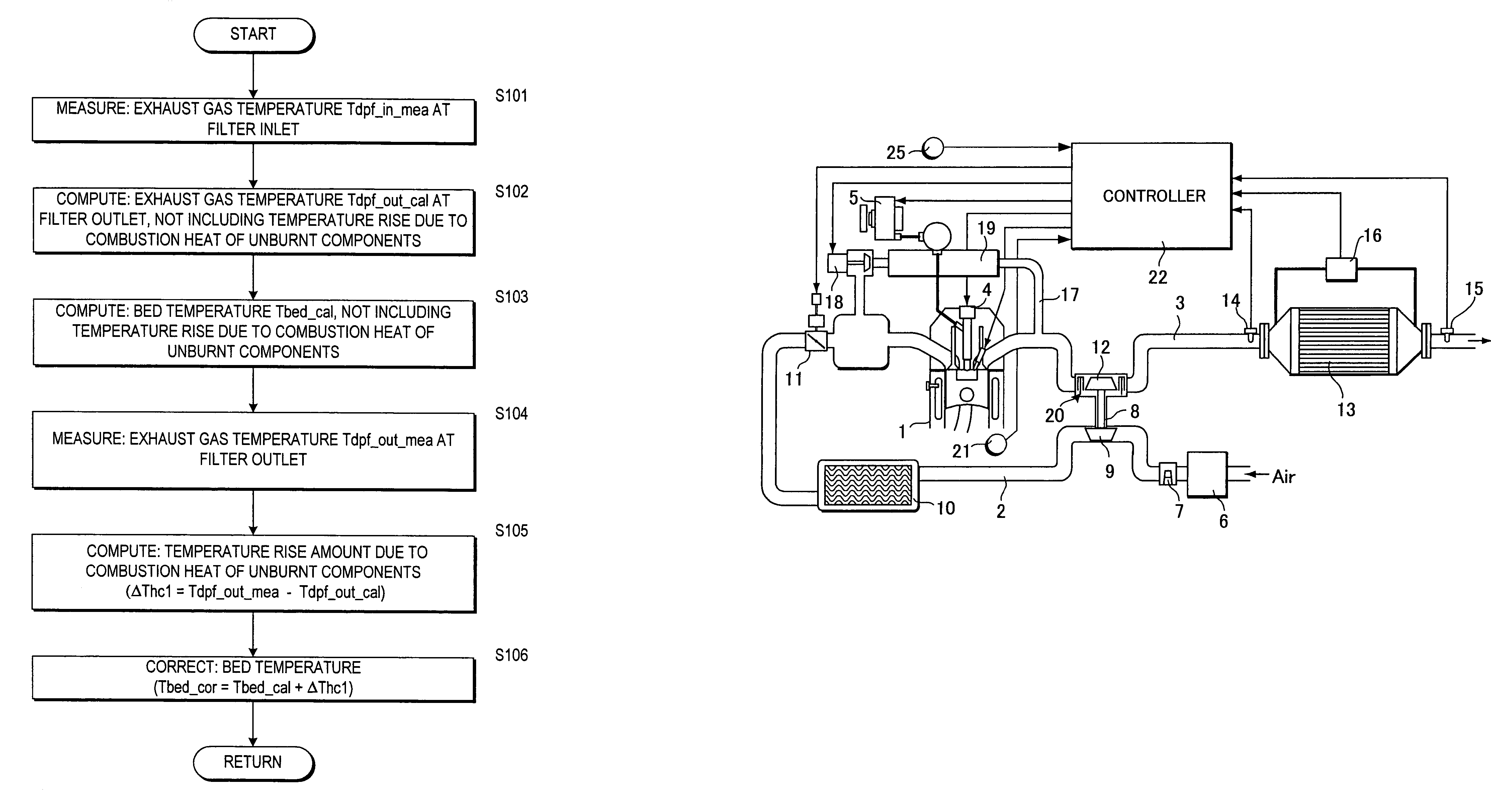
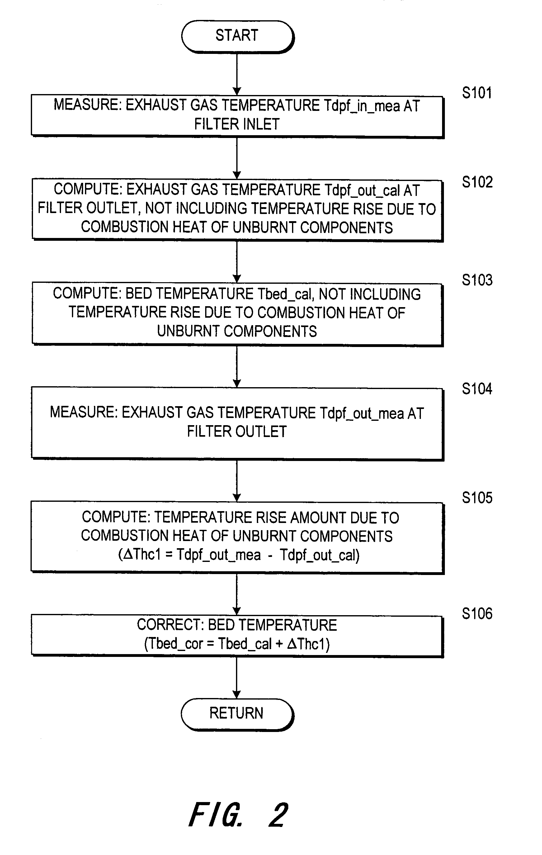
[0023]Referring to FIG. 2, the control routine relating to the bed temperature computation performed by the controller 22 will now be described. This control routine is periodically performed, for example by a timer interrupt at a fixed interval of 10 milliseconds.

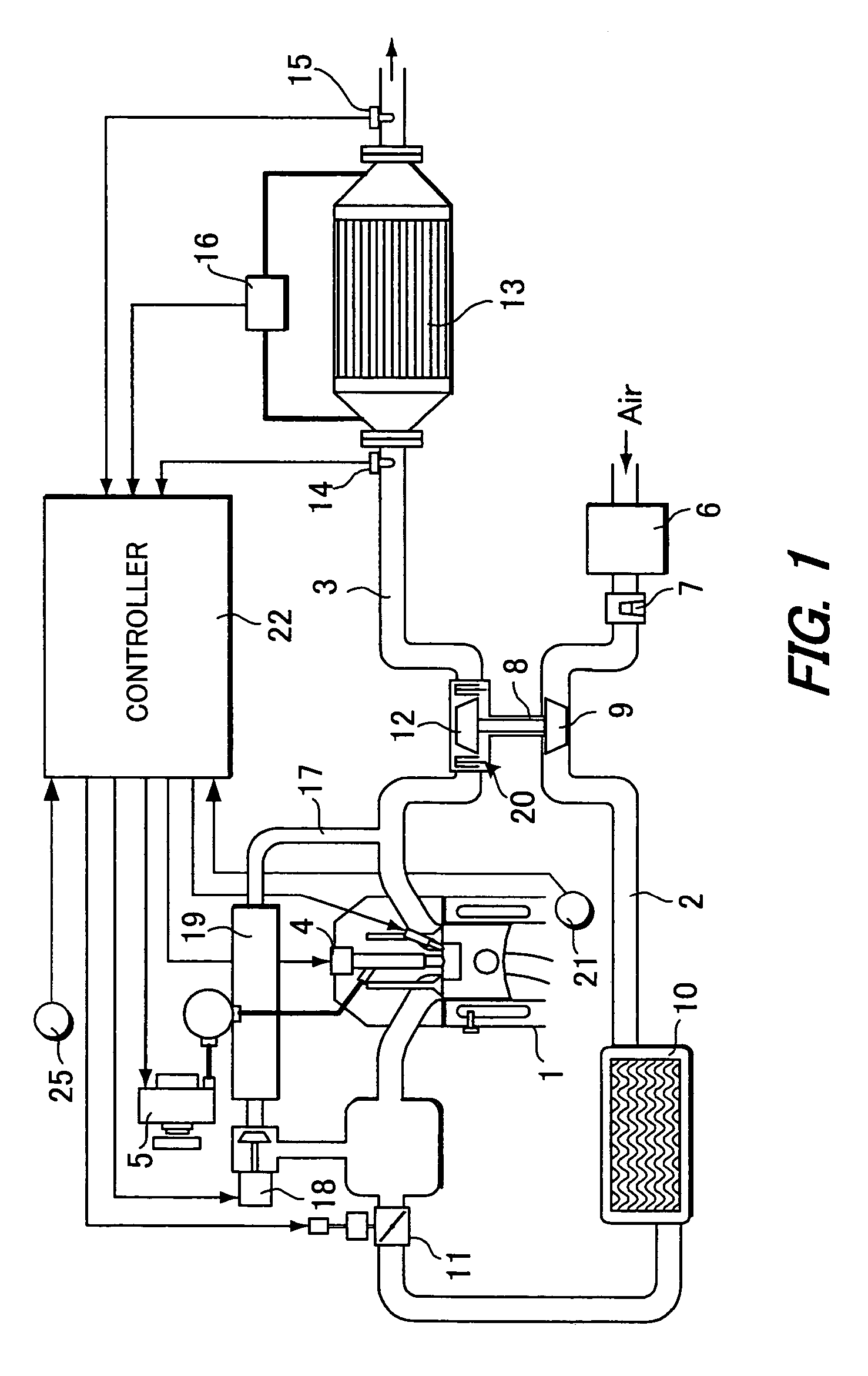
[0024]In a step S101, an exhaust gas temperature Tdpf_in_mea of the filter inlet side is measured based on a signal from the temperature sensor 14.

[0025]Next, in a step S102, an exhaust gas temperature Tdpf_out_cal on the filter outlet side assuming that there is no combustion of unburnt components, is computed using the measured inlet temperature Tdpf_in_mea. The outlet temperature Tdpf_out_cal can be estimated from the engine running state and measured inlet temperature Tdpf_in_mea. For example, the fuel injection amount Q and engine rotation speed Ne showing the the engine running state, and the inlet temperature Tdpf_in_mea, are used as parameters, and the outlet temperature Tdpf_out_cal is calculated by referring to a...

second embodiment

[0034]Referring to the flowchart of FIG. 4, the control routine relating to the bed temperature computation performed by the controller 22, will now be described. The processing of the step S101-step S103 is identical to that of FIG. 2, and the outlet temperature Tdpf_out_cal and the bed temperature Tbed_cal which do not contain the temperature rise due to the combustion heat of unburnt components are computed based on the measured inlet temperature Tdpf_in_mea.

[0035]This embodiment differs from the first embodiment in that a temperature rise amount ΔTch2 due to the recaction of unburnt components is computed from the unburnt component amount.

[0036]In a step S204, the discharge rate of HC and CO which are unburnt components is first calculated by referring to a map. The discharge rate (which is a discharge amount in a fixed interval) of unburnt components is determined by the engine running state. Therefore, a map which gives the discharge rate of unburnt components from an engine r...


PUM


Abstract

A regeneration control device, which regenerates a filter (13) for trapping particulate matter in exhaust gas from an engine (1), is disclosed. The filter (13) supports a catalyst which oxidizes unburnt components in the exhaust gas. The regeneration control device has a temperature sensor (14) which detects a filter inlet exhaust gas temperature (Tdpf_in_mea); and a microcomputer (22). The microcomputer (22) is programmed to compute a filter outlet exhaust gas temperature (Tdpf_out_cal), not including temperature rise due to oxidation reaction of unburnt components based on the detected inlet exhaust gas temperature; compute the filter bed temperature (Tbed_cal) based on the detected inlet exhaust gas temperature and computed outlet exhaust gas temperature; compute a temperature rise (ΔThc1) due to oxidation reaction of unburnt components; correct the bed temperature based on the computed temperature rise (ΔThc1).

Description

FIELD OF THE INVENTION[0001]This invention relates an engine exhaust gas purification device, and more specifically to the improvement of a technique for regenerating a filter which traps particulate matter in engine exhaust gas.BACKGROUND OF THE INVENTION[0002]JP-A-H5-106427 published by the Japan Patent Office in 1993 discloses a filter for an engine exhaust gas system to purify particulate matter (hereafter, referred to as “exhaust gas particulates”) discharged from an engine such as a diesel engine. The filter is regenerated by oxidizing or burning the trapped exhaust gas particulates at a predetermined interval. Regeneration of the filter is performed by raising the exhaust gas temperature. The increase of exhaust gas temperature is achieved by engine control, such as applying an angle retardation to the fuel injection timing or performing a secondary injection in addition to the main injection.[0003]The temperature of the filter surface on which particulates are deposited is r...

Claims


Application Information

Patent Timeline
Patent Type & Authority Patents(United States)
IPC IPC(8): F01N3/00F02M25/06F02N3/02F01N3/023F01N9/00F02B3/06F02B29/04F02D41/02F02M25/07
CPCF01N3/023F02D41/029F01N9/002Y02T10/47F01N2430/08F01N2560/06F01N2560/08F01N2560/14F02B3/06F02B29/0406F02B37/00F02B2275/14F02D41/1446F02D2200/0804F02M25/0707F02M25/0727Y02T10/123Y02T10/42F02M26/05F02M26/23Y02T10/12Y02T10/40
Inventor UENO, SHOUICHIROUKAWASHIMA, JUNICHIOTAKE, MAKOTOKONDOU, TERUNORITSUTSUMOTO, NAOYAINOUE, TAKAOKOGA, TOSHIMASA
Owner NISSAN MOTOR CO LTD
Why Eureka
Try Eureka