Linear motion guide unit

a technology of motion guide and guide trough, which is applied in the direction of linear bearings, shafts and bearings, bearings, etc., can solve the problems of complex work, complicated configuration, and difficult and complex accuracy of cutting the guide trough throughout the recirculation circuit of the slider, so as to facilitate the assembly of the slider and the effect of accurate cutting and keeping the load area

a technology of motion guide and guide trough, which is applied in the direction of linear bearings, shafts and bearings, bearings, etc., can solve the problems of complex work, complicated configuration, and difficult and complex accuracy of cutting the guide trough throughout the recirculation circuit of the slider, so as to facilitate the assembly of the slider and the effect of accurate cutting and keeping the load area

US7066650B2Active Publication Date: 2006-06-27NIPPON THOMPSON

Image

  • Linear motion guide unit
  • Linear motion guide unit
  • Linear motion guide unit

Examples


embodiment 1

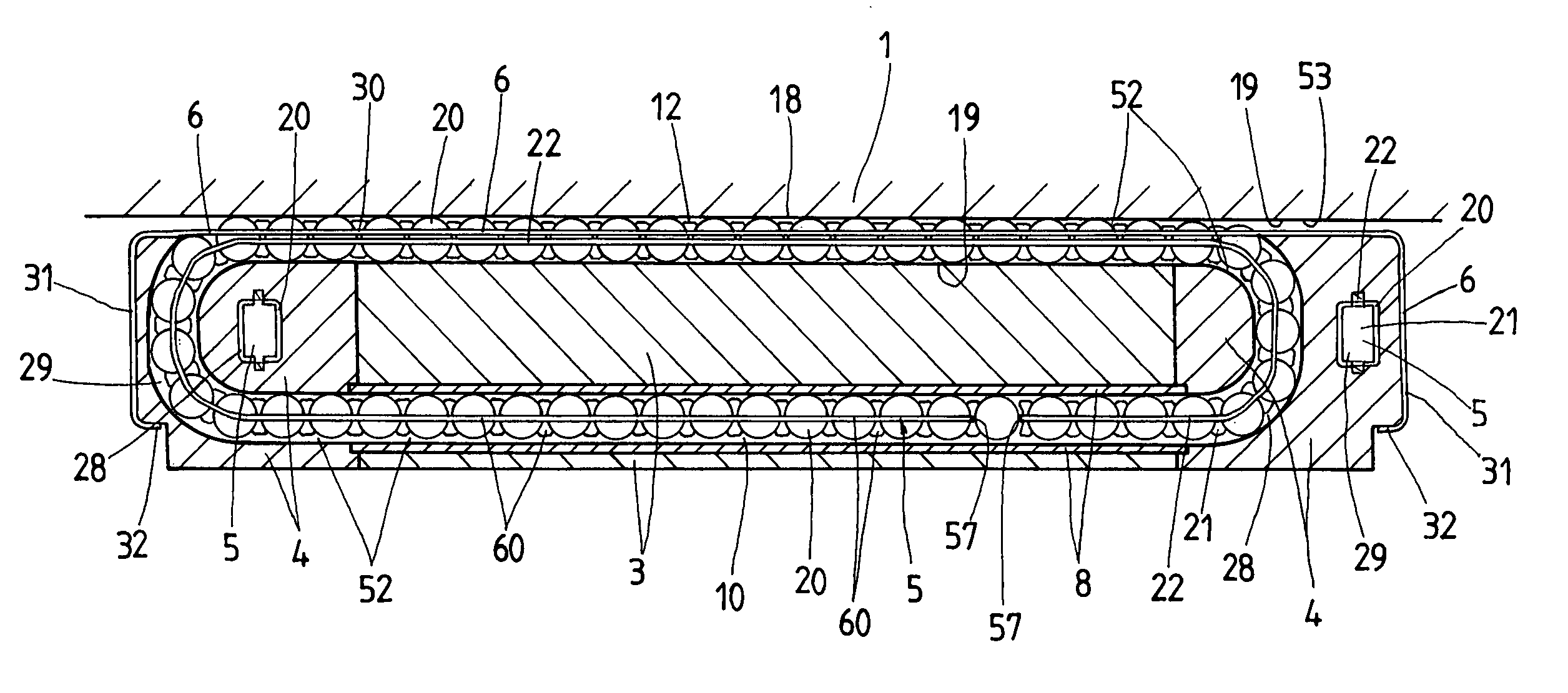
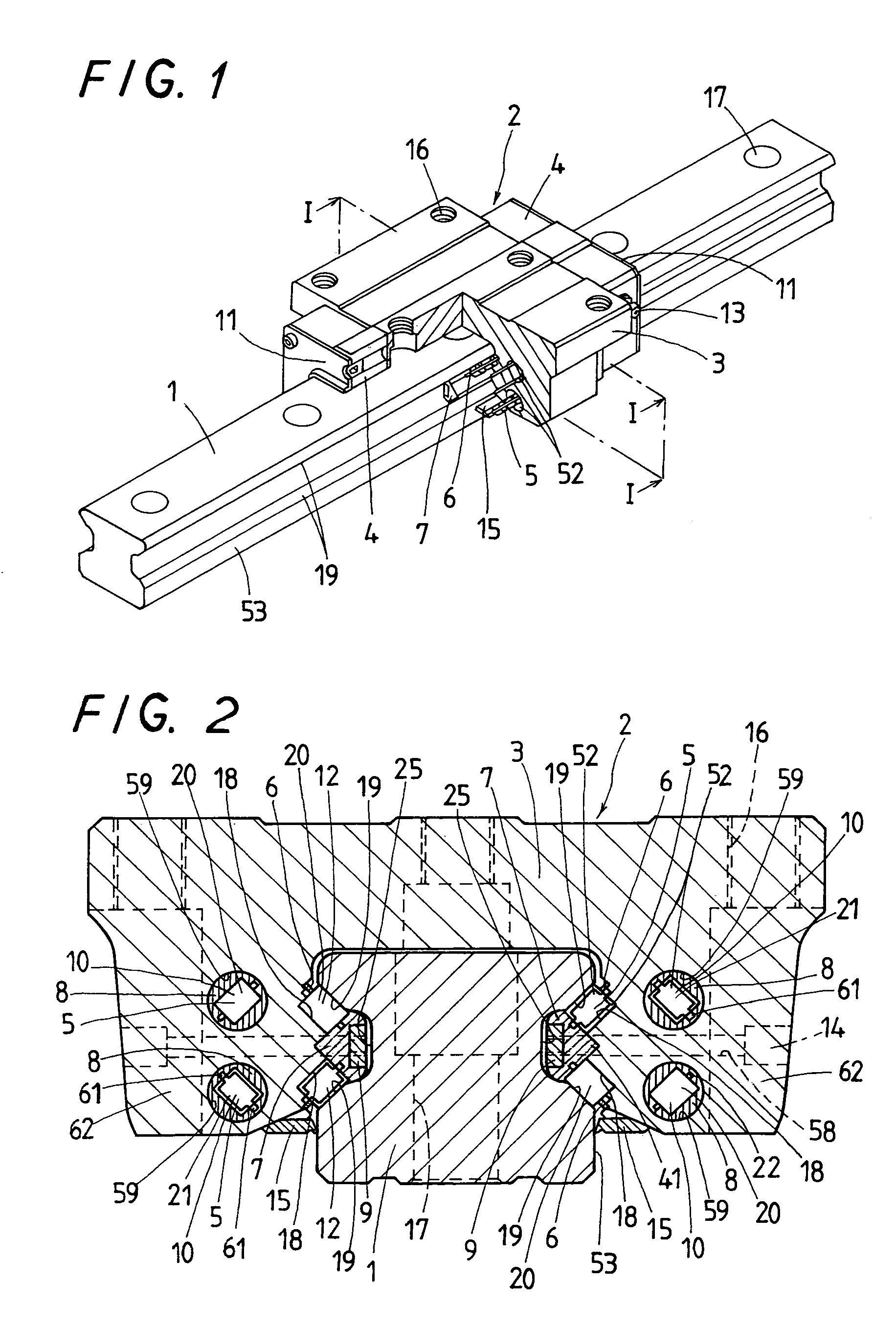
[0062]With the linear motion guide unit of the first embodiment constructed as in FIGS. 2 to 13, the retainer plate 7 for keeping the rollers 20 is secured to the carriage 3 of the slider 2 with using fastening bolts 14. The retainer plate 7 extends in the fore-and-aft direction of the carriage 3 and has lengthwise guide surfaces 45, which come into sliding contact with any axial ends of the rollers 20 to carry axially them for rolling through the load races 12 of the recirculation circuits 52. The retainer plate 7 is also made on the guide surfaces 45 thereof with guide troughs 23, one to each guide surface, for carrying the links 22 of the roller chains 5. The retainer plate 7 is made on the back thereof with a recess 42 to receive therein a backup plate 9 having threaded holes 55. The retainer plate 7 is further bored at 39 between upper and lower guide surfaces 45 extending in parallel with one another. The recess 42 cut in the retainer plate 7 has a depth somewhat more than the...

embodiment 2

[0066]With the second embodiment as in FIGS. 14 to 21, the first embodiment constructed as stated earlier is modified by replacing the backup plate 9 with a fastener band 46 to secure a retainer plate 7A to end caps 4A. The modified linear motion guide unit has not to use the fastening bolts applied from the outside of the carriage 3 for fastening the retainer plate 7A upon assembly. Thus, the use of the fastener band 46 would make assembly and dismantlement of the roller chain 5 out of the recirculation circuit 52 easier. Moreover, there is no need of making any bolt holes in the retainer plate 7A and the carriage 3. Like the retainer band 6, the fastener band 46 may be easily made by simple bending operation to form a thin metal strip into a desired shape. No need of through-holes for fastening gives an advantage to the linear motion guide unit that requires the use of tiny rolling-element chain.

[0067]For completing assembly of the slider 2, the retainer plate 7A fits into the V-g...


PUM


Abstract

A linear motion guide unit is disclosed in which there is provided a retainer band making it possible to easily fit a roller chain with rollers traveling through a recirculation circuit into a load way of the recirculation circuit, thereby making sure of smooth recirculation of the roller chain. Cooperation of the retainer band with a retainer plate helps guide links of the roller chain in a load way of the recirculation circuit, keeping the roller chain against running out of the load way thereby ensuring smooth movement of the roller chain throughout the recirculation circuit.

Description

FIELD OF THE INVENTION[0001]The present invention relates generally to a linear motion guide unit comprised of a guide rail and a slider that fits over the guide rail for linear movement relative to and along the guide rail by virtue of rolling elements that are allowed to run through a recirculation circuit made in the slider and, more particularly, to a linear motion guide unit of the construction as state earlier, in which the rolling elements fit for rolling motion in the circulation circuit in a way connected with one another through a chain to control their behavior.BACKGROUND OF THE INVENTION[0002]There is conventionally known a linear motion guide unit having a rolling-element chain in which rolling elements are held in a chain to control the behavior of the rolling elements during the rolling motion through the recirculation circuit. The slider is made therein with a guide trough extending along the overall recirculation circuit to fit therein the chain of the rolling-eleme...

Claims


Application Information

Patent Timeline
27 Jun 2006
Publication
US7066650B2
IPC
F16C29/06; F16C19/22; F16C33/46; F16C33/50; F16C33/58; F16C33/60
CPC
F16C29/0607; F16C33/506; F16C29/065
Inventors
ISHIHARA, TOYOHISA