Pipeline heater

a technology for heating equipment and pipes, applied in mechanical equipment, light and heating equipment, machines/engines, etc., can solve the problems of less efficient water bath heaters, significant noise, and health risks to people, pets and properties, and achieves increased fluid residence time, increased heat transfer, and quiet operation.

Active Publication Date: 2006-06-27
CATALYTIC INDAL GROUP
View PDF4 Cites 41 Cited by
  • Summary
  • Abstract
  • Description
  • Claims
  • Application Information

AI Technical Summary

Benefits of technology

[0007]In another aspect, the inventive pipeline heater comprises an inlet manifold presenting a diameter D1, a pipe section presenting a diameter D2, a plurality of flameless catalytic IR emitters positioned about the pipe section, and an outlet manifold presenting a diameter D3, with D2 being greater than each of D1 and D3. Unless otherwise specified, the term “diameter” as used herein in relation to the manifolds and pipe section refer to the inner diameter of the structures through which the fluid stream flows. Preferably, D2 is at least 50% greater, more preferably at least about 100% greater, even more preferably at least about 200% greater, and most preferably at least about 400% greater than each of D1 and D3. In this manner, the pipe section forms a “volume bottle” which serves to slow the fluid flow rate through the heater thereby increasing the residence time of the fluid in the heater and allowing for greater heat transfer to occur. For example, in the instance where D1 is about 2 inches, D2 can be up to about 8 inches, or when D1 is about 4 inches, D2 can be about 10 inches.
[0008]The pipes section used to conduct the pipeline fluid through the heater can be a relatively straight section thereby making a single pass through the heater, or the pipe section can be serpentine thereby making multiple passes through the heater. In the case of multiple passes, each pass has a plurality of flameless catalytic IR emitters positioned thereabout, and preferably in a substantially diamond-shaped configuration. Because the catalytic emitters do not produce a flame, the heaters operate much more quietly than conventional water bath-type heaters and can be safely used in virtually any location. Also, the use of automation equipment allows for remote operation of the heater.

Problems solved by technology

These types of heaters have the drawback in that the fire tubes produce significant amounts of noise and ethylene glycol presents health risks to people, pets, and property.
In addition, water bath heaters tend to be less efficient because the heat transfer occurs through an intermediate medium, namely the water bath.

Method used


Image

  • Pipeline heater
  • Pipeline heater
  • Pipeline heater

Examples


Embodiment Construction

[0018]The following examples set forth preferred pipeline heaters in accordance with the present invention. It is to be understood, however, that these examples are provided by way of illustration and nothing therein should be taken as a limitation upon the overall scope of the invention.

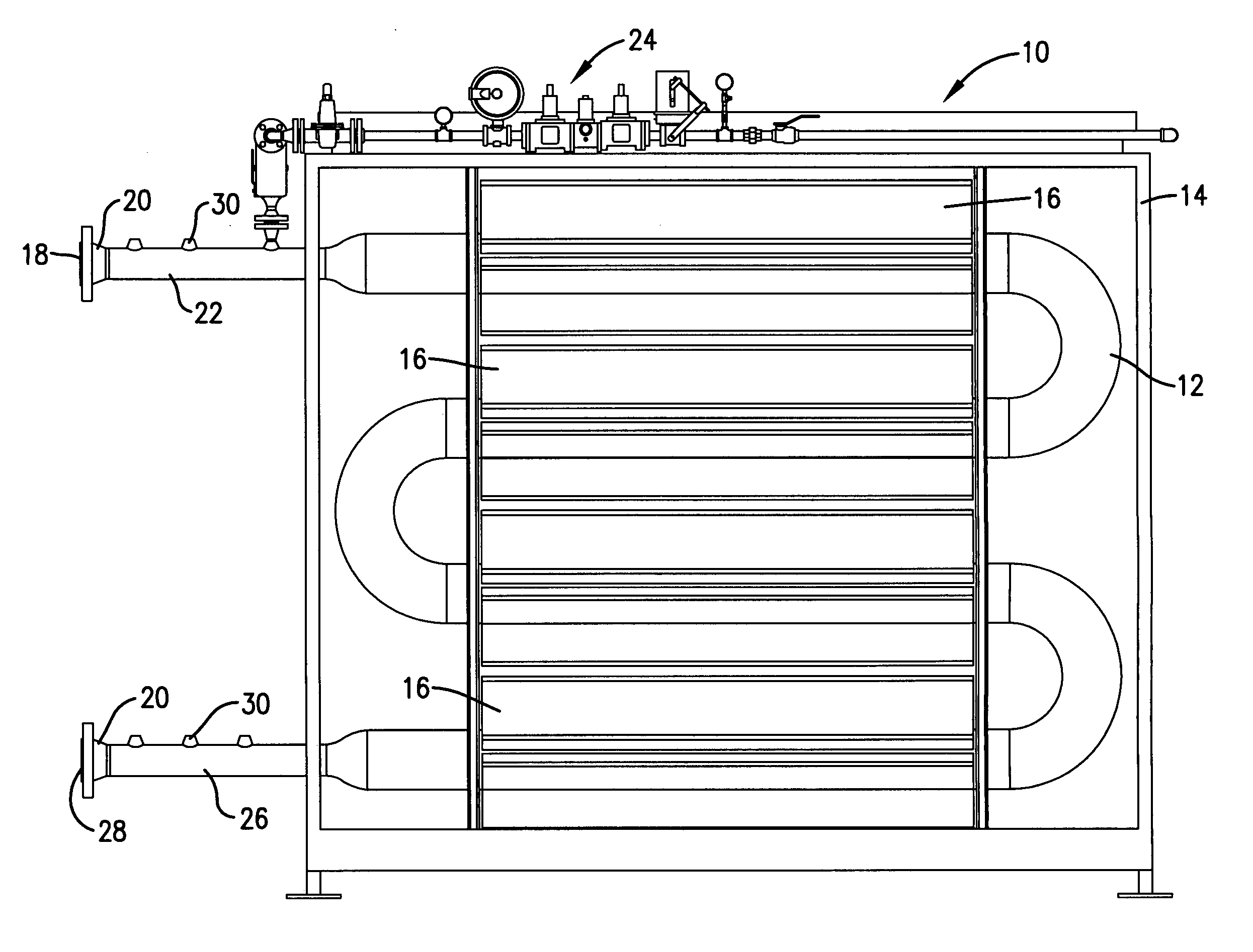
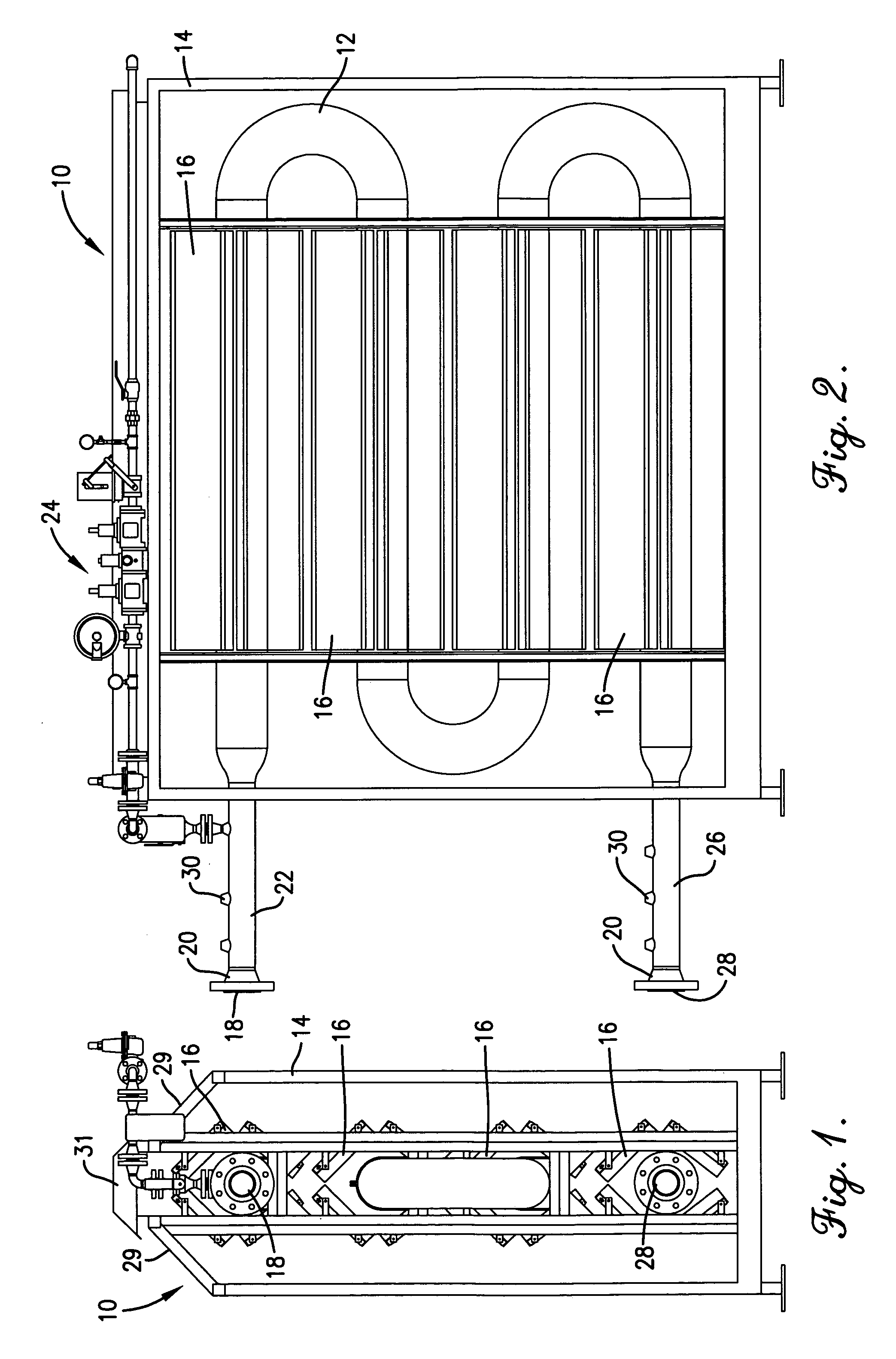
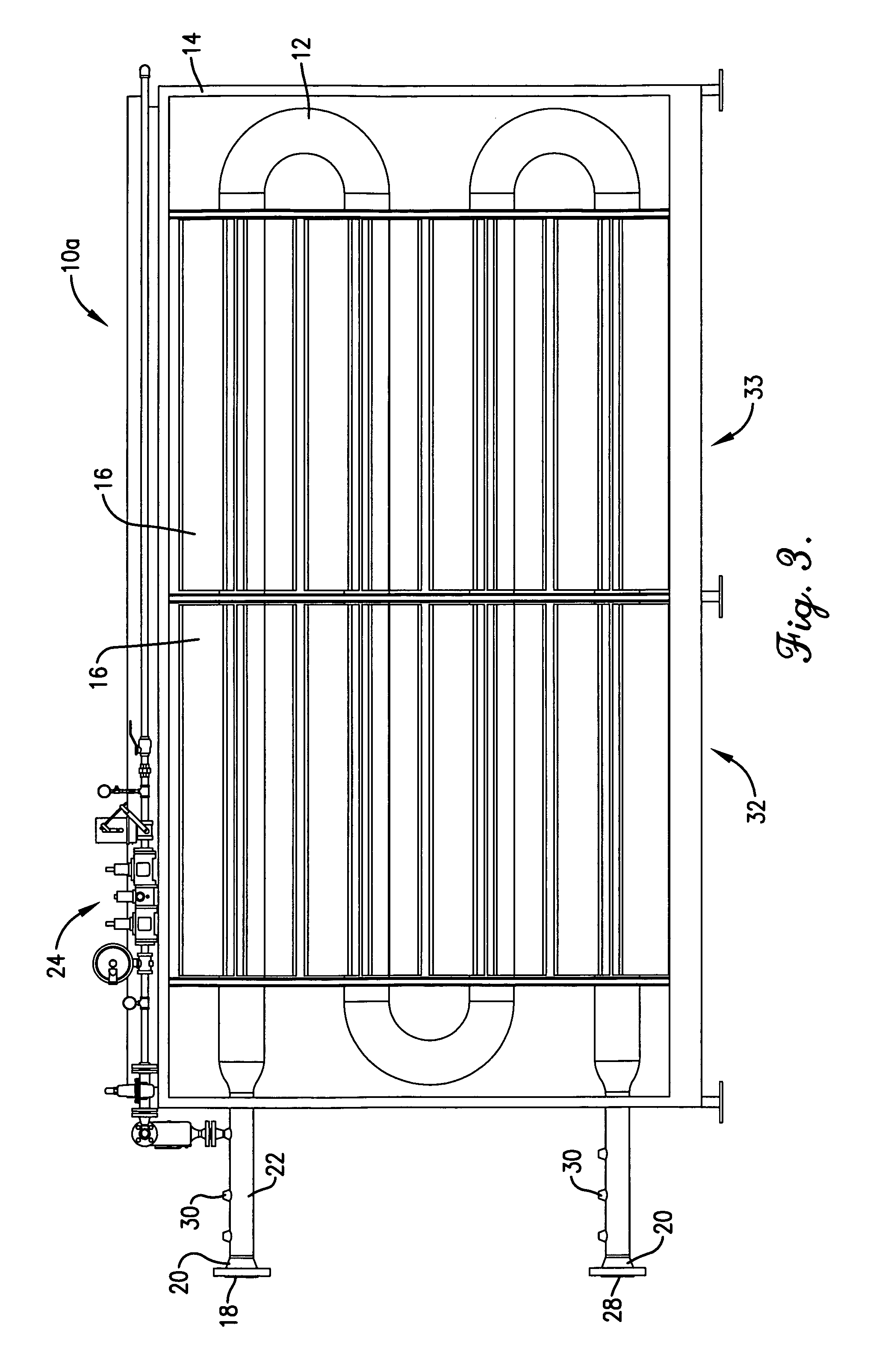
[0019]Turning now to the drawings, and in particular FIGS. 1 and 2 which depict a four-pass pipeline heater 10, heater 10 generally comprises a serpentine pipe 12 located within a heater housing 14. Each pass of coil 12 is surrounded by a plurality of catalytic IR emitters 16 arranged in a diamond-shaped pattern. Emitters 16 are generally flameless, gas-fired elements that provide heat in the form of infrared energy. Exemplary emitters include those described in U.S. Pat. Nos. 5,557,858 and 6,003,244, both of which are incorporated by reference herein. Such catalytic emitters are also available from Catalytic Industrial Group, Inc. of Independence, Kans.

[0020]The diamond-shaped emitter arrangement a...


PUM


Abstract

A pipeline heater comprising a plurality of flameless catalytic IR emitters positioned about a section of pipe in a substantially diamond-shaped configuration, the diameter of the pipe section being greater than the diameters of the heater inlet and outlet manifolds in order to increase the residence time of the fluid within the heater. The pipeline heater may comprise a single or multiple passes of the pipe section therethrough, each pass having a plurality of catalytic emitters positioned thereabout in a substantially diamond-shaped configuration.

Description

BACKGROUND OF THE INVENTION[0001]1. Field of the Invention[0002]The present invention generally pertains to a pipeline heating apparatus and methods of heating gas and liquid streams using the same. The inventive pipeline heaters employ flameless, catalytic IR emitters positioned about a section of pipe which is in the form of a volume bottle for increasing the residence time of the fluid in the heater.[0003]2. Description of the Prior Art[0004]Pipeline heaters are used to heat gas and liquids flowing through a pipeline in order to prevent regulators and various sensing equipment from freezing up during pipeline operation. Traditionally, water bath indirect heaters have been used for this purpose. In water bath heaters, a vessel is filed with water or a mixture of water and ethylene glycol. A fire tube and process coil are submerged in the bath which transfers heat from the fire tube to the process stream in the coil. These types of heaters have the drawback in that the fire tubes p...

Claims


Application Information

Patent Timeline
Patent Type & Authority Patents(United States)
IPC IPC(8): F22B15/00
CPCF22D1/003F22B1/22
Inventor MACALUSO, VIRGIL
Owner CATALYTIC INDAL GROUP
Why Eureka
Try Eureka