
Chain ring protector

Inactive Publication Date: 2006-06-27
EKO SPORT
View PDF11 Cites 38 Cited by
  • Summary
  • Abstract
  • Description
  • Claims
  • Application Information

AI Technical Summary

Benefits of technology

[0010]Accordingly, despite the benefits of the known chain ring protectors, there remains a need for a simple, cost effective, easy to install and adjust, chain ring protector that can be operably secured to a large number of vehicles independent of a particular frame design, and that can effectively protect any sized chain ring operably installed on a vehicle without interfering with operation of the vehicle. In addition to other benefits that will become apparent in the following disclosure, the present invention fulfills these needs.
[0012]Preferably, the durable guard is detachably secured to the mounting bracket, and the mounting bracket includes a plurality of mounting portions thereon, thereby allowing a large variety of possible mounting configurations for the durable guard. More preferably, the guard includes parallelly aligned slots extending therethrough for operably engaging the mounting portions, thereby allowing the outer edge of the durable guard to be adjusted simply by sliding the durable guard along the slots toward or away from the bottom bracket sleeve.
[0013]Since the durable guard is detachably secured to the mounting bracket, the durable guard may be replaced easily if it becomes damaged or worn, or if a different sized durable guard is desired.

Problems solved by technology

However, portions of most chain rings remain exposed and extend below the bicycle frame.
Accordingly, chain rings are susceptible to bending and damage caused by inadvertent impact with objects.
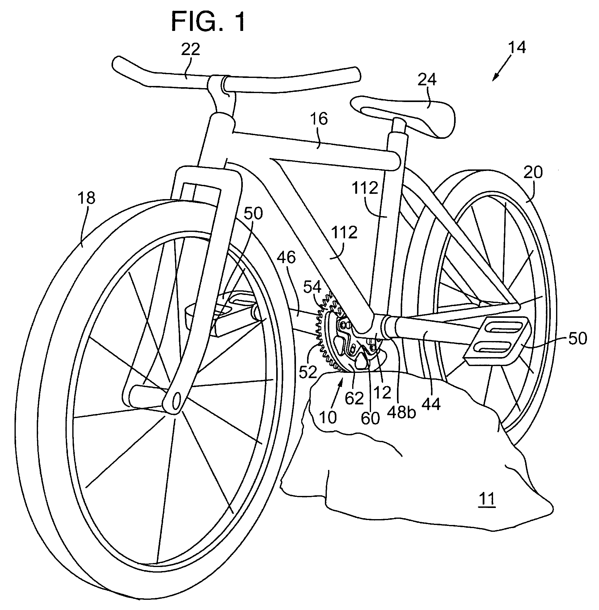
If the rider executes a jump and in the process lands the bicycle such that a large rock straddles the front and rear wheels, the chain ring can impact the rock causing damage to the chain ring.
Attempts to protect the chain ring from inadvertent impacts have had limited success.
However, since the circular disk is directly connected to the chain ring and drive shaft, any bending or damage of the circular disk caused by the impact will likely also bend the attached chain ring or drive shaft.
Moreover, such circular disks offer negligible protection from impacts to the chain ring arising from contact with objects positioned toward the inside surface of the chain ring.
Despite the benefits of the Morales design, it has several drawbacks.
For example, a large amount of hardware, such as the first and second clamps, pivot structure, and struts, is required to support the protector, thereby increasing the expense of the structure and time required to mount and align it properly.
Accordingly, the first and second clamps and orientation taught in Morales may not be operable when attempting to install the Morales protector on these different frame structures.
Also, if the struts are too long, the trough-type protector can interfere with operation of the bicycle.
In addition, under some impacts on the trough-type protector, the swivel structure can actually allow the trough-type protector to deflect into to the chain ring, thereby damaging it, or at least forcing the rider to stop to realign the protector.

Method used


Image

  • Chain ring protector
  • Chain ring protector
  • Chain ring protector

Examples


Embodiment Construction

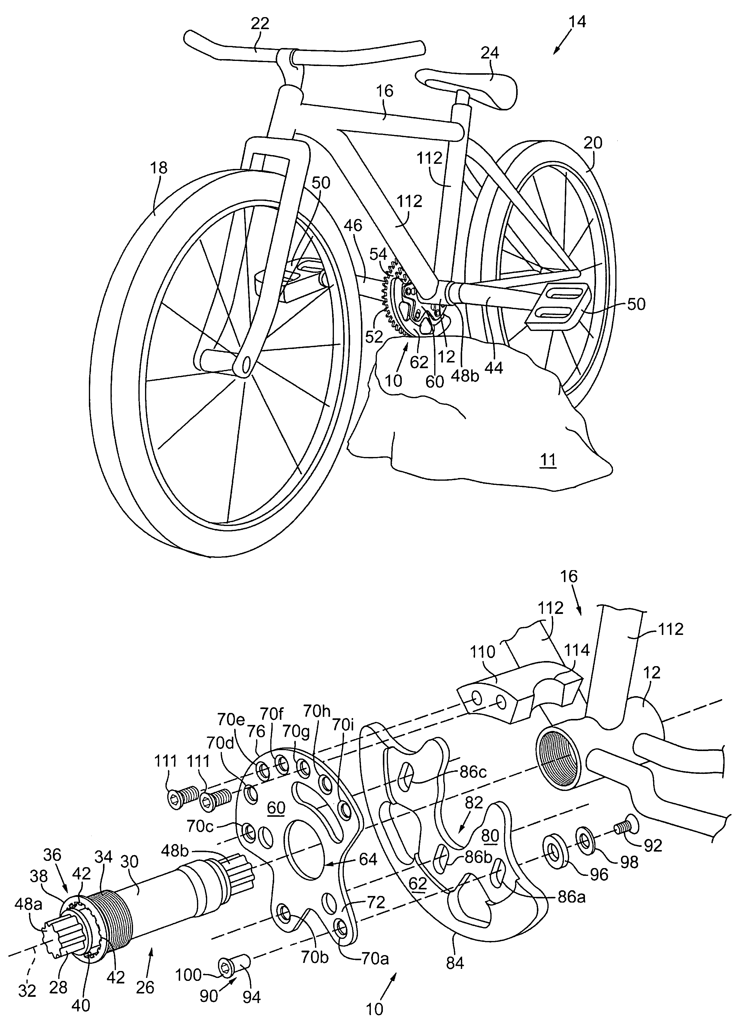
[0022]A simple, cost effective, easy to install and adjust, chain ring protector 10 operably secured to the lower bracket sleeve 12 of a vehicle, such as a bicycle 14, is shown in FIGS. 1–5B.

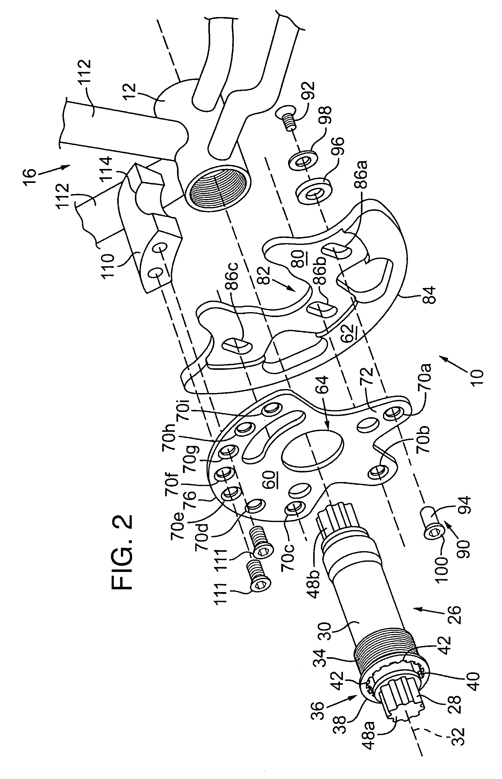
[0023]Referring to FIG. 1, the bicycle 14 includes a frame 16 having a front wheel 18, back wheel 20, handle bars 22, seat 24, and the lower bracket sleeve 12 operably secured thereto. Preferably, the lower bracket sleeve 12 is reverse threaded to accept the threads of a conventional lower bracket spindle 26 (FIG. 2) therethrough. The lower bracket spindle 26 is a common, commercially available product, and includes a shaft 28 operably received within a housing 30. The shaft 28 rotates about a longitudinal centerline 32. Usually, bearings (not shown) are sealed within the housing 30 to facilitate rotation of the shaft 28.

[0024]Preferably, the housing 30 includes the reverse threads 34 toward one end 36 with a lip 38 adjacent to those threads 34. More preferably, the housing 30 also includes a re...


PUM


Abstract

A chain ring protector having a substantially planar mounting bracket operably secured to the bottom bracket sleeve of a vehicle with a durable semi-circumferential guard extending therefrom is disclosed. The durable guard has a substantially arcuate outer edge sized to approximate the outer diameter of a chain ring, and it is operably secured to the planar mounting bracket such that the outer edge extends slightly beyond the outer diameter of the portion of the chain ring extending below the bottom bracket sleeve.

Description

FIELD OF THE INVENTION[0001]The present invention relates to a protector for chain rings on bicycles and the like. In particular, it includes a mounting bracket operably secured to the bottom bracket sleeve with a durable guard extending therefrom and detachably secured thereto.BACKGROUND OF THE INVENTION[0002]Wheeled vehicles and especially in-line, two-wheeled vehicles such as bicycles, motorcycles, scooters, and the like, are popular forms of transportation, exercise, and sport. More recently, such vehicles are being used in particularly rugged environments including operating over unimproved roads and rough terrain, and for stunt riding over stairs and the like. For example, a form of bicycle commonly known as a mountain bike is specifically intended for off-road operation.[0003]Most two-wheeled vehicles are propelled by a chain operably extending between two or more sprockets. One sprocket, commonly known as a chain ring, is driven by a power source such as a crank and pedal as...

Claims


Application Information

Patent Timeline
IPC IPC(8): B62J23/00B62K19/44
CPCB62K19/44B62J23/00B62J13/00B62J15/02
Inventor ROGERS, JAMES K.
Owner EKO SPORT
Learn More