
Anesthetic metering system

a technology of anaesthesia and metering system, which is applied in the direction of respirator, other medical devices, inhalator, etc., can solve the problems of unintended burden on the person present, easy spillage of part of the anaesthesia added during refilling, and inability to meet the needs of patients,

Inactive Publication Date: 2006-06-27
DRAGERWERK AG
View PDF9 Cites 12 Cited by
  • Summary
  • Abstract
  • Description
  • Claims
  • Application Information

AI Technical Summary

Benefits of technology

[0004]Therefore, the object of the present invention is to provide an improved anesthetic metering system, which overcomes the drawbacks of the prior-art systems, on the one hand, and additionally makes it possible to refill the anesthetic reservoir at the anesthetic manufacturer.
[0006]One essential advantage of the subject according to the invention follows from the use of an anesthetic reservoir, into which a propellant is admitted and has a liquid anesthetic reserve separated by a flexible partition. Due to the cooperation of the anesthetic reservoir designed as described with the components of an anesthesia apparatus according to the invention, an anesthetic metering system is created, which makes it possible to rapidly change used anesthetic reservoirs and to refill these reservoirs at the anesthetic manufacturer. The hitherto usual complicated filling of the reservoirs of anesthetic evaporators at the clinical workplace, which is potentially hazardous to the health of the workers, is eliminated due to the anesthetic metering system according to the present invention.

Problems solved by technology

Such reservoirs are usually installed permanently at the anesthetic evaporator and are refilled according to relatively complicated and time-consuming techniques with a filling tube, a filling adapter or a funnel.
The fact that part of the anaesthetic added during refilling is easily spilled and unintendedly burdens the persons present due to evaporation into the ambient air is especially disadvantageous.

Method used


Image

  • Anesthetic metering system
  • Anesthetic metering system

Examples


Embodiment Construction

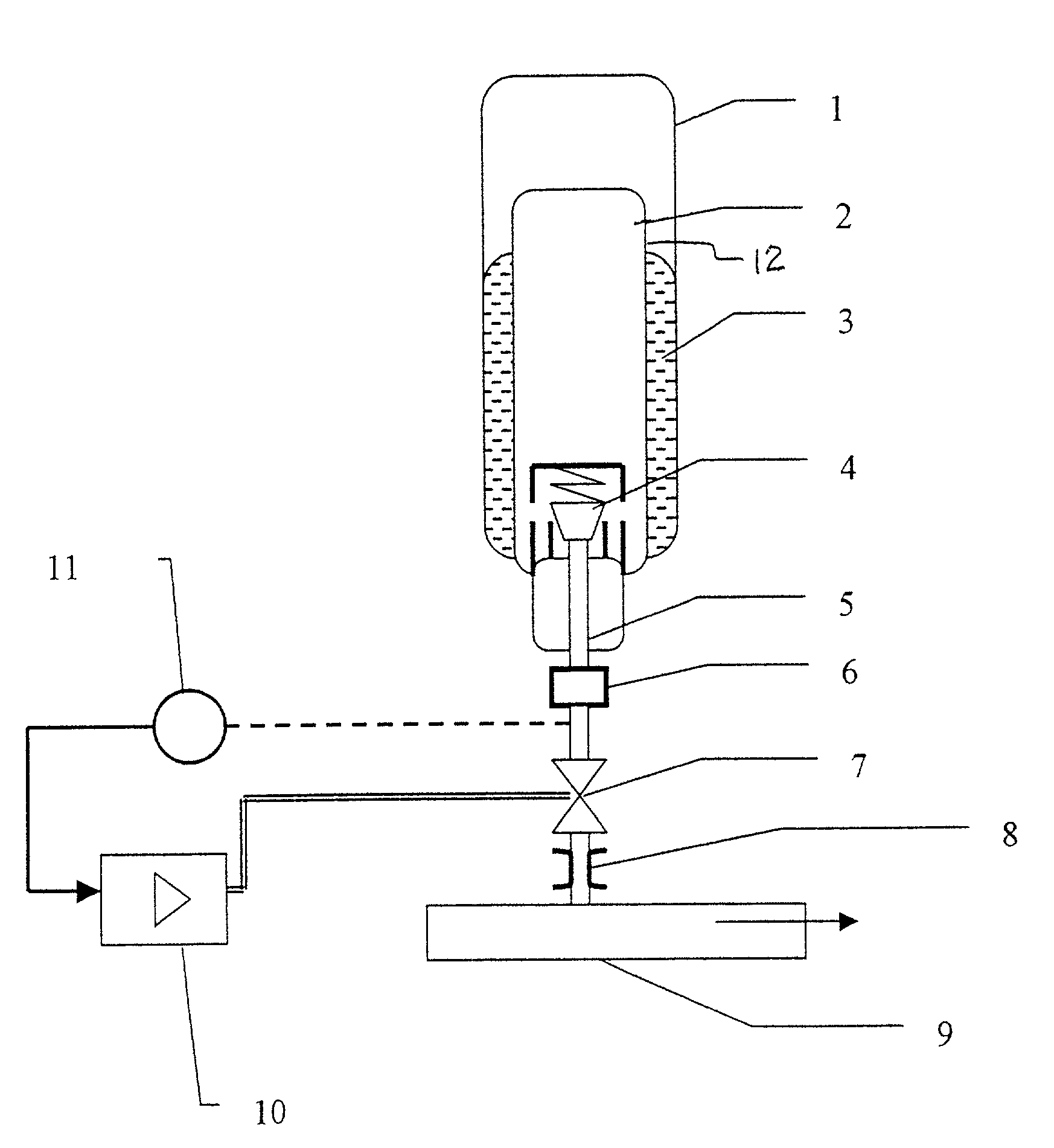
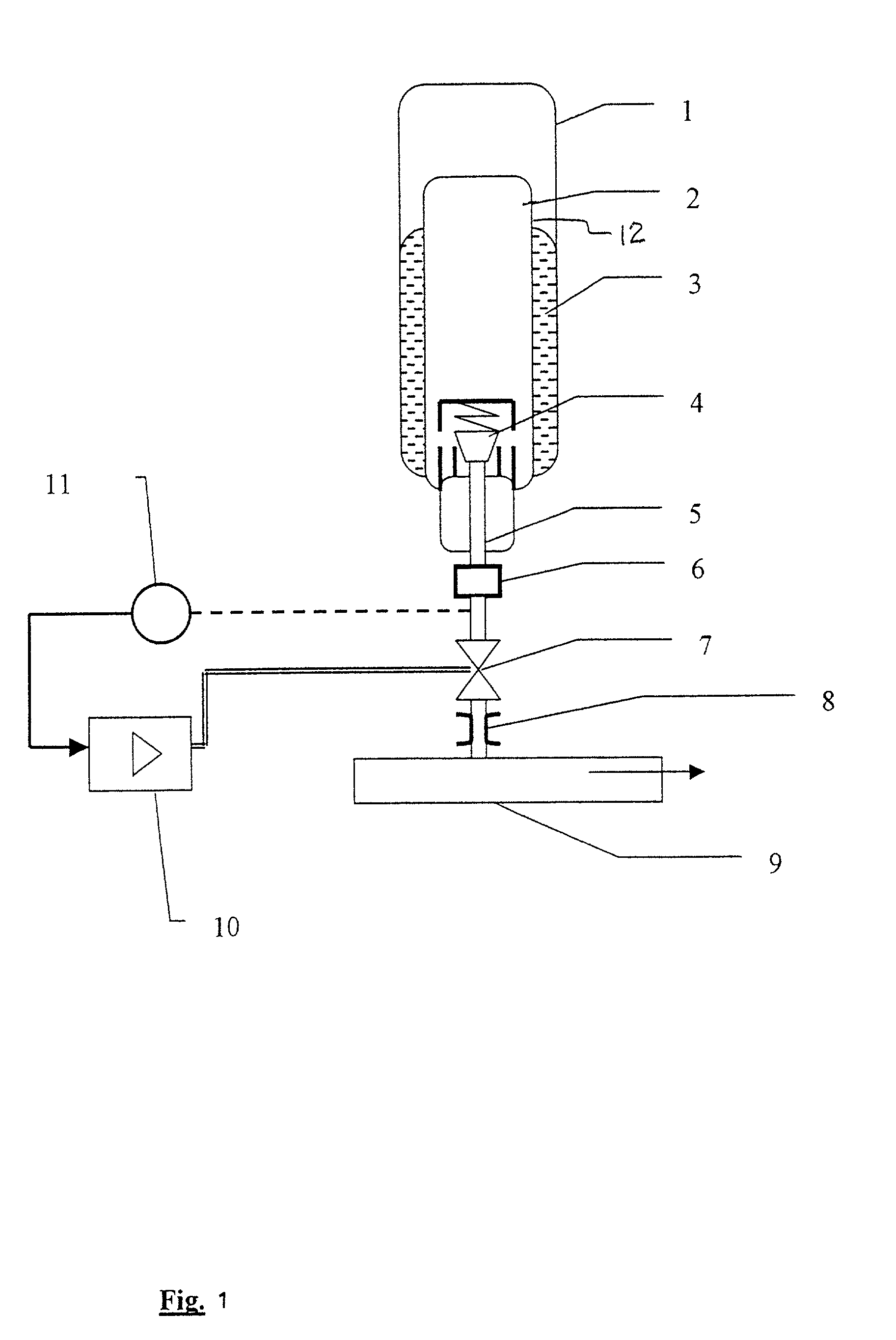
[0016]Referring to the drawings in particular, a pressure-resistant anesthetic reservoir 1, made especially of aluminum, has a liquid anesthetic reserve 2 limited by means of an impermeable, flexible material wall 12. The flexible material wall 12 consists especially of aluminum, polyethylene or a metal-coated, flexible plastic laminate, which must be resistant to the anesthetic being used on the inside and to the propellant 3 used on the outside. The anesthetic reserve 2 and the propellant 3 are separated by the wall 12 defining a propellant space separate from the anesthetic reserve. The propellant 3 pressurizes the anesthetic via the wall material 12. Heptafluoropropane or another suitable propellant gas, such as nitrogen, is preferably used as the propellant 3. The anesthetic reservoir 1 is equipped with a first valve 4, which is shown as a mechanically actuated lifting valve in the FIGURE. The first valve 4 is in flow connection with the pressurized liquid anesthetic reserve 2 ...


PUM


Abstract

An anesthetic metering system includes an anesthetic reservoir (1) having an anesthetic reserve (2), which is limited by a flexible material wall and to which pressure is admitted by means of a propellant (3) acting thereon via the wall material. The anesthetic reservoir (1) has a first valve (4), which is in flow connection with the liquid anesthetic reserve (2) and can be inserted into a mounting element (6) of an anesthesia apparatus. The metered release of anesthetic to the anesthesia apparatus takes place via a volumetric nozzle (8). The present invention provides an anesthetic metering device which avoids, on the one hand, the drawbacks of the anesthetic evaporators used previously, which are to be refilled with anesthetics at the workplace, and makes possible the refilling of the anesthetic reservoir (1) at the anesthetic manufacturer, on the other hand.

Description

CROSS REFERENCE TO RELATED APPLICATIONS[0001]This application claims the benefit of priority under 35 U.S.C. § 119 of German Patent Application DE 101 21 004.3-44 filed Apr. 28, 2001.FIELD OF THE INVENTION[0002]The present invention pertains to an anesthetic metering system, method and device with an anesthetic reservoir having a liquid anesthetic reserve.BACKGROUND OF THE INVENTION[0003]Prior-art anesthetic metering systems, e.g., that described in EP 0 449 545 A1, have, in general, an anesthetic evaporator with an associated reservoir with a liquid anesthetic reservoir. Such reservoirs are usually installed permanently at the anesthetic evaporator and are refilled according to relatively complicated and time-consuming techniques with a filling tube, a filling adapter or a funnel. The fact that part of the anaesthetic added during refilling is easily spilled and unintendedly burdens the persons present due to evaporation into the ambient air is especially disadvantageous.SUMMARY OF...

Claims


Application Information

Patent Timeline
IPC IPC(8): A61M5/155A61M15/00A61M16/18
CPCA61M16/18A61M15/009
Inventor KULLIK, GOTZKOCH, JOCHIM
Owner DRAGERWERK AG
Learn More