Platform link wrist mechanism

Inactive Publication Date: 2006-06-27
INTUITIVE SURGICAL OPERATIONS INC
View PDF19 Cites 179 Cited by
  • Summary
  • Abstract
  • Description
  • Claims
  • Application Information

AI Technical Summary

Benefits of technology

[0025]In a second aspect of the present invention, the robotic surgical tool includes a tool base disposed near the proximal end of the shaft. The tool base includes mechanisms for actuating the wrist mechanism and often mechanisms for actuating the end effector. Mechanisms for actuating the wrist mechanism includes mechanisms for advancing or retracting the first rod. In some embodiments, such mechanisms comprises a first rotational actuation member to which the first rod is attached so that rotation of the first rotational actuation member advances or retracts the first rod. Typically, another rod is attached to the first rotational actuation member in a position diametrically opposite to the first rod so that rotation of the first rotational actuation member simultaneously advances the first rod and retracts the diametrically opposite rod. In some embodiments, the tool base further comprises a second rotational actuation member to which the second rod is attached so that rotation of the second rotational actuation member advances or retracts the second rod substantially along the axial direction. Again, another rod is often attached to the second rotational actuation member in a position diametrically opposite to the second rod so that rotation of the second

Problems solved by technology

Thus, an increased adoption of minimally invasive techniques could save millions of hospital days and millions of dollars annually in hospital residency costs alone.
There are many disadvantages relating to current MIS technology.
For example, existing MIS instruments deny the surgeon the flexibility of tool placement found in open surgery.
Most current laparoscopic tools have rigid shafts, so

Method used


Image

  • Platform link wrist mechanism
  • Platform link wrist mechanism
  • Platform link wrist mechanism

Examples


Embodiment Construction

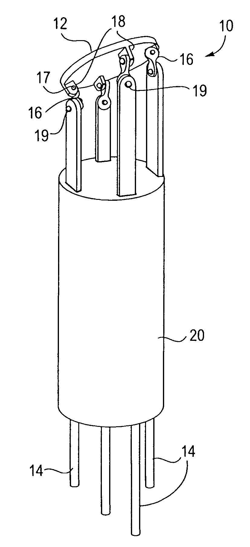
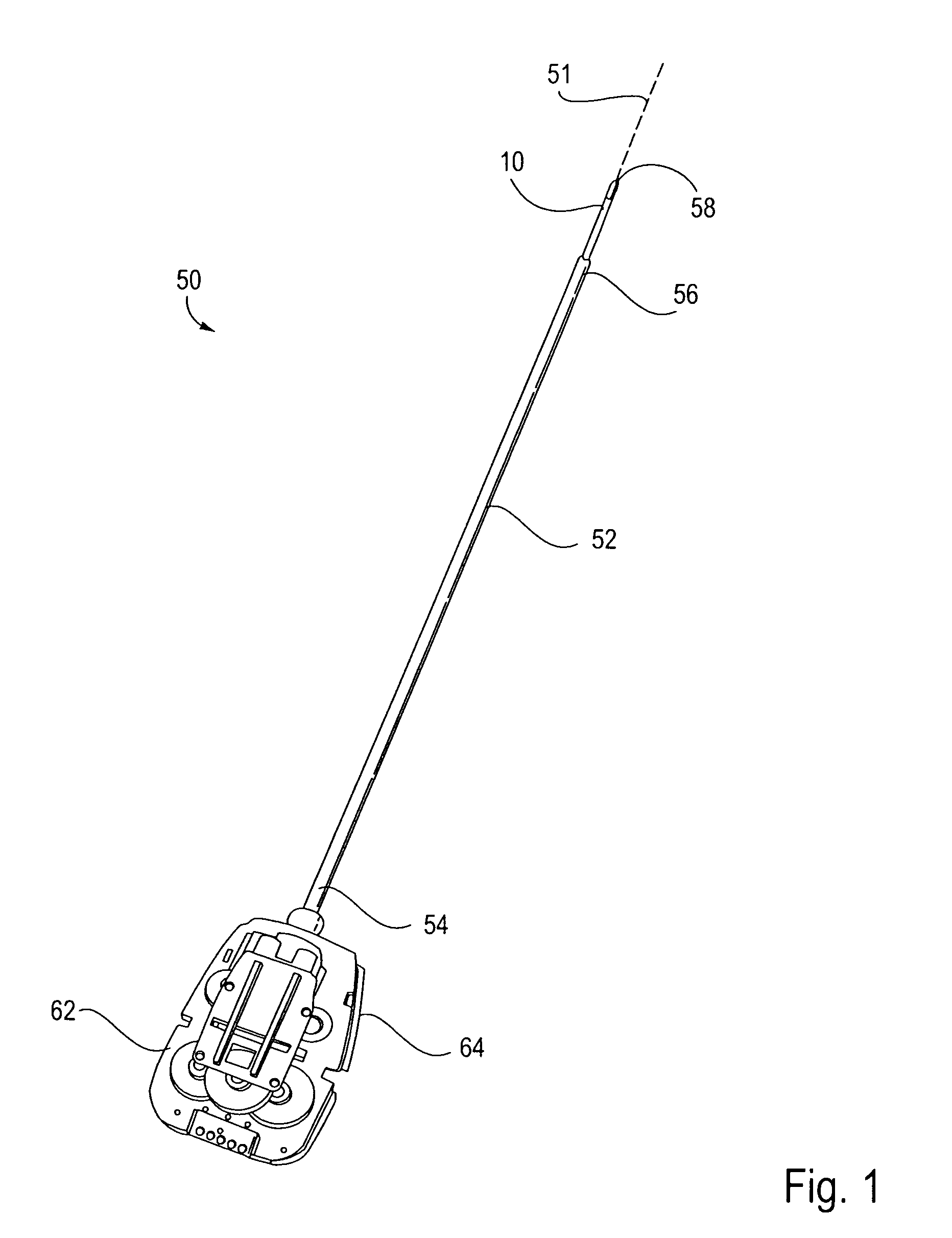
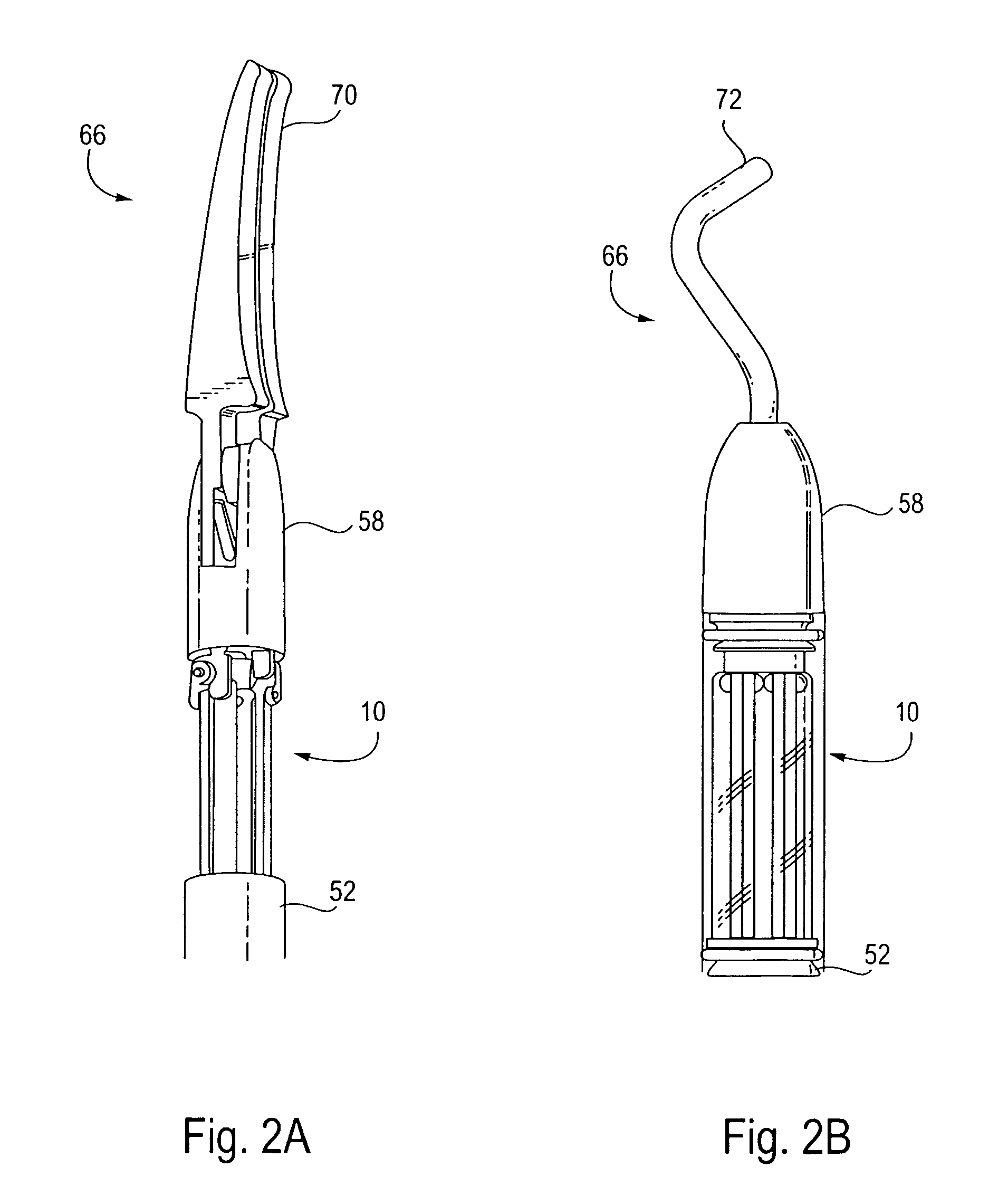
[0061]FIG. 1 illustrates a surgical tool 50 of the present invention which is used in robotic surgery systems. The surgical tool 50 includes a rigid shaft 52 having a proximal end 54, a distal end 56 and a longitudinal axis therebetween. The proximal end 54 is coupled to a tool base 62. The tool base 62 includes an interface 64 which mechanically and electrically couples the tool 50 to a manipulator on the robotic arm cart. A distal member, in this embodiment a distal clevis 58, is coupled to shaft 52 by a wrist joint or wrist mechanism 10, the wrist mechanism 10 providing the distal clevis 58 with at least 1 degree of freedom and ideally providing at least 3 degrees of freedom. The distal clevis 58 supports a surgical end effector 66, the actual working part that is manipulable for effecting a predetermined treatment of a target tissue. Exemplary surgical end effectors 66 are illustrated in FIGS. 2A–2B. Grasping jaws 70 are illustrated in FIG. 2A, while a cautery isolation effector...


PUM


Abstract

The present invention provides a robotic surgical tool for use in a robotic surgical system to perform a surgical operation. The robotic surgical tool includes a wrist mechanism disposed near the distal end of a shaft which connects with an end effector. The wrist mechanism includes a distal member configured to support the end effector, and a plurality of rods extending generally along an axial direction within the shaft and movable generally along this axial direction to adjust the orientation of the distal member with respect to the shaft. Advancement or retraction of a first rod generally along the axial direction tips the base through a first angle. The addition of a second angle allows the distal member to direct the end effector in essentially a compound angle. The robotic surgical tool may also include provisions for roll movement.

Description

CROSS-REFERENCES TO RELATED APPLICATIONS[0001]This application is a continuation of U.S. patent application Ser. No. 10 / 186,176 , filed on Jun. 28,2002, now U.S. Pat. No. 6,699,235, which was based on and claimed the benefit of U.S. Provisional Patent Application No. 60 / 301,967, filed Jun. 29, 2001, and U.S. Provisional Patent Application No. 60 / 327,702, filed Oct. 5, 2001, the entire disclosures of which are incorporated herein by reference.[0002]This application is related to the following patents and patent applications, the full disclosures of which are incorporated herein by reference:[0003]PCT International Application No. PCT / US98 / 19508, entitled “Robotic Apparatus”, filed on Sep. 18, 1998, and published as WO99 / 50721;[0004]U.S. patent application Ser. No. 09 / 418,726, entitled “Surgical Robotic Tools, Data Architecture, and Use”, filed on Oct. 15, 1999;[0005]U.S. Patent Application No. 60 / 111,711, entitled “Image Shifting for a Telerobotic System”, filed on Dec. 8, 1998;[0006...

Claims


Application Information

Patent Timeline
IPC IPC(8): A61B17/00A61B19/00A61B17/28A61B34/30B25J17/02
CPCA61B19/22A61B17/00234A61B19/2203A61B2017/2929A61B2017/2934A61B2019/2226Y10S606/914A61B2019/2242A61B2019/2249Y10T74/20335Y10T74/20317Y10T74/20305A61B2019/2234A61B34/70A61B34/71A61B34/30A61B2034/304A61B2034/305A61B34/72
Inventor WALLACE, DANIEL T.ANDERSON, S. CHRISTOPHERMANZO, SCOTT
Owner INTUITIVE SURGICAL OPERATIONS INC
Why Eureka
Try Eureka