
Structure and method to reduce drain induced barrier lowering

a technology of drain induced barrier and structure, which is applied in the direction of basic electric elements, electrical apparatus, and semiconductor devices, can solve the problems of increasing potential gradients, increasing leakage current, and reducing the total power consumption of flash devices and products using flash devices, so as to reduce dibl and reduce net impurity concentration

Inactive Publication Date: 2006-06-27
INFINEON TECH LLC
View PDF2 Cites 4 Cited by
  • Summary
  • Abstract
  • Description
  • Claims
  • Application Information

AI Technical Summary

Benefits of technology

[0014]Accordingly, what is needed is a structure and method for reducing DIBL without complicating the manufacture process. The structure and method for reducing DIBL should utilize established semiconductor manufacturing equipment. In addition, the structure and method for reducing DIBL should facilitate in maintaining precise critical dimensions for small-scale semiconductor manufacturing.

Problems solved by technology

Increases in leakage current may have a significant deleterious effect on total power consumption of the flash device and the product using the flash device.
Unfortunately, increasing dopant within the body deleteriously increases potential gradients in the ensuing device.
Typically, high DIBL results in current leakage during high voltage programming.
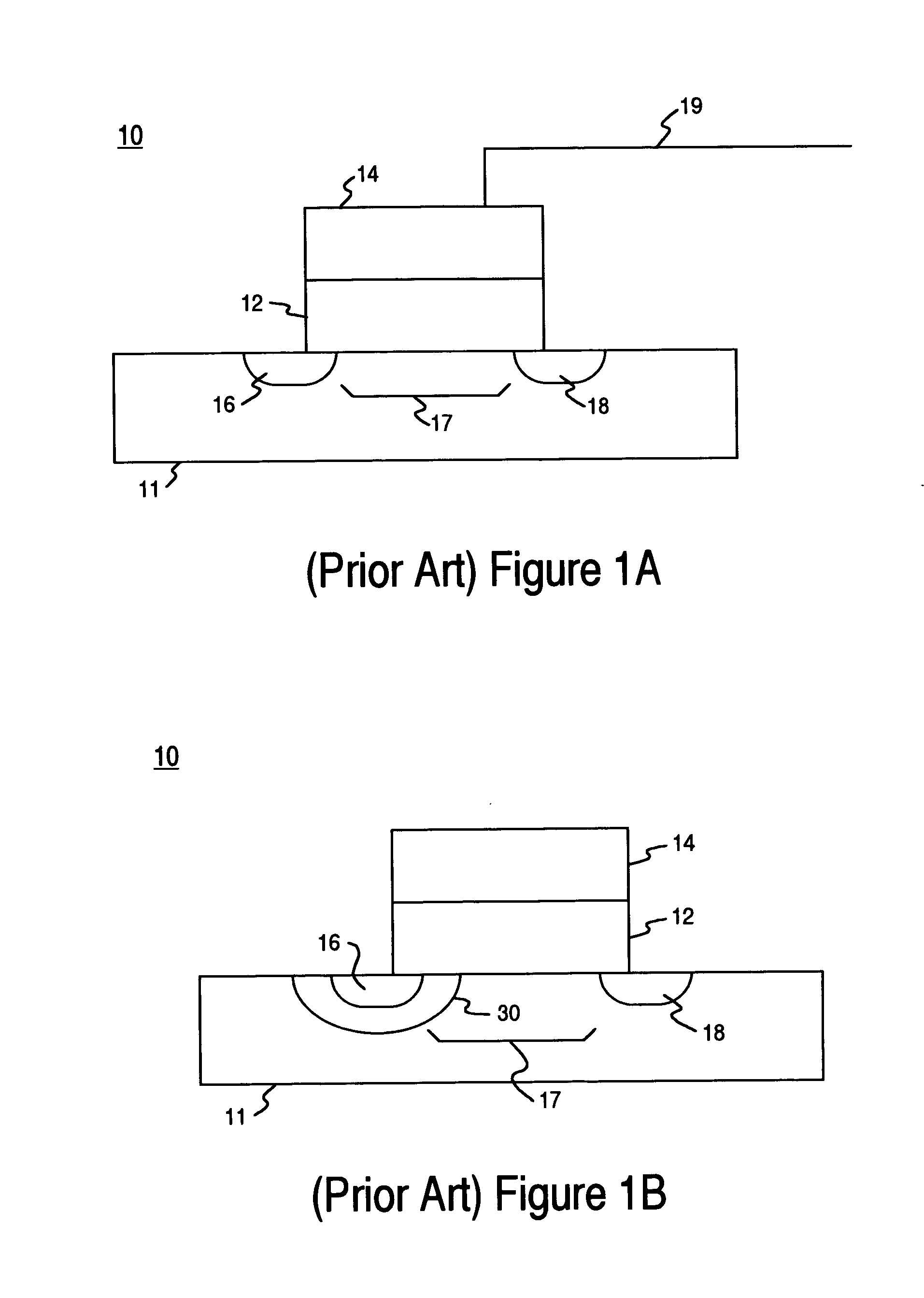
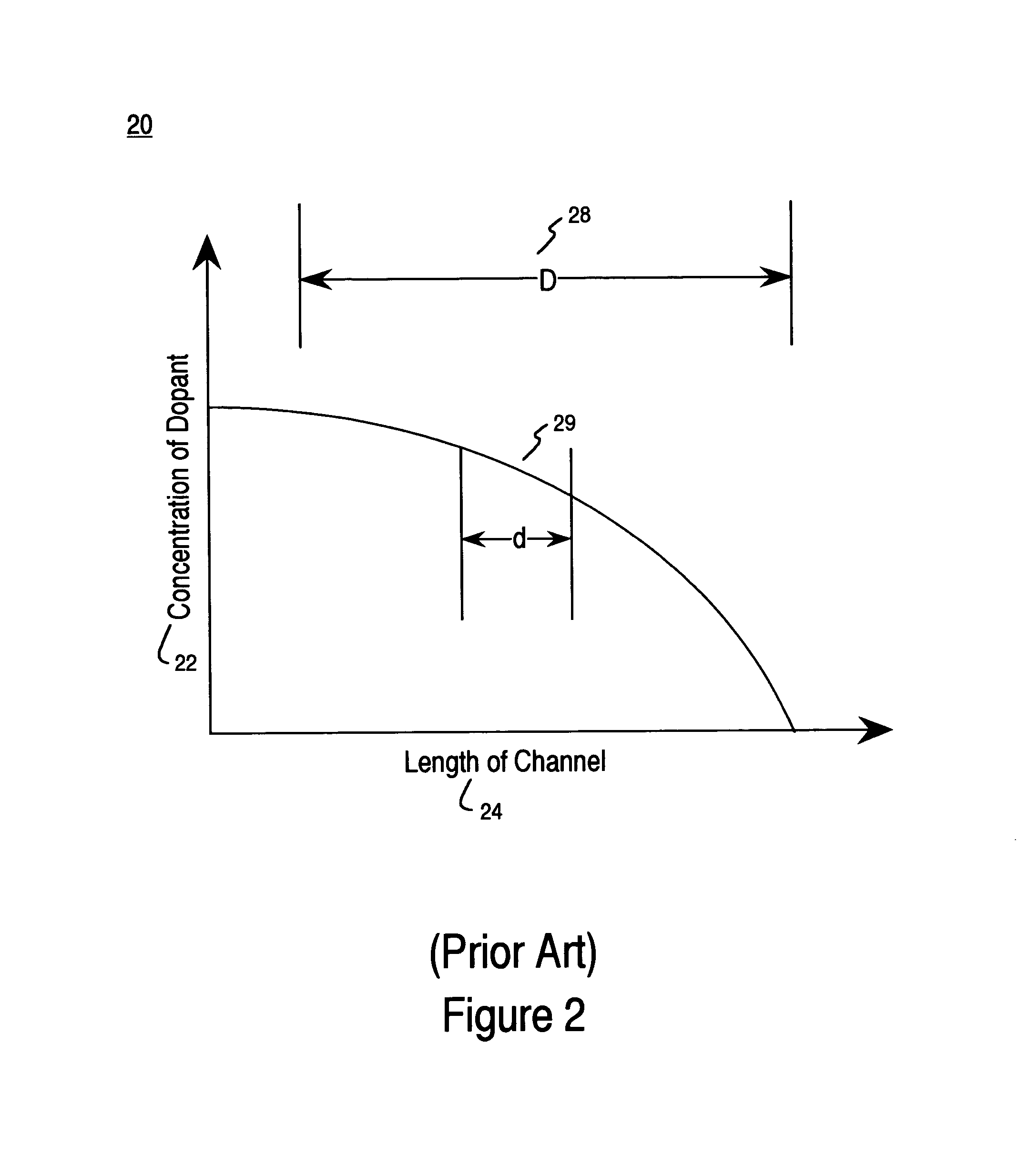
As a result of the small channel length, the dopant concentration is virtually flat across the channel, thus resulting in poor reduction of DIBL.

Method used


Image

  • Structure and method to reduce drain induced barrier lowering
  • Structure and method to reduce drain induced barrier lowering
  • Structure and method to reduce drain induced barrier lowering

Examples


Embodiment Construction

[0032]Reference will now be made in detail to the preferred embodiments of the invention, examples of which are illustrated in the accompanying drawings. While the invention will be described in conjunction with the preferred embodiments, it will be understood that they are not intended to limit the invention to these embodiments. On the contrary, the invention is intended to cover alternatives, modifications and equivalents, which may be included within the spirit and scope of the invention as defined by the appended claims. Furthermore, in the following detailed description of the present invention, numerous specific details are set forth in order to provide a thorough understanding of the present invention. However, it will be obvious to one of ordinary skill in the art that the present invention may be practiced without these specific details. In other instances, well-known methods, procedures, and components have not been described in detail as not to unnecessarily obscure aspe...


PUM


Abstract

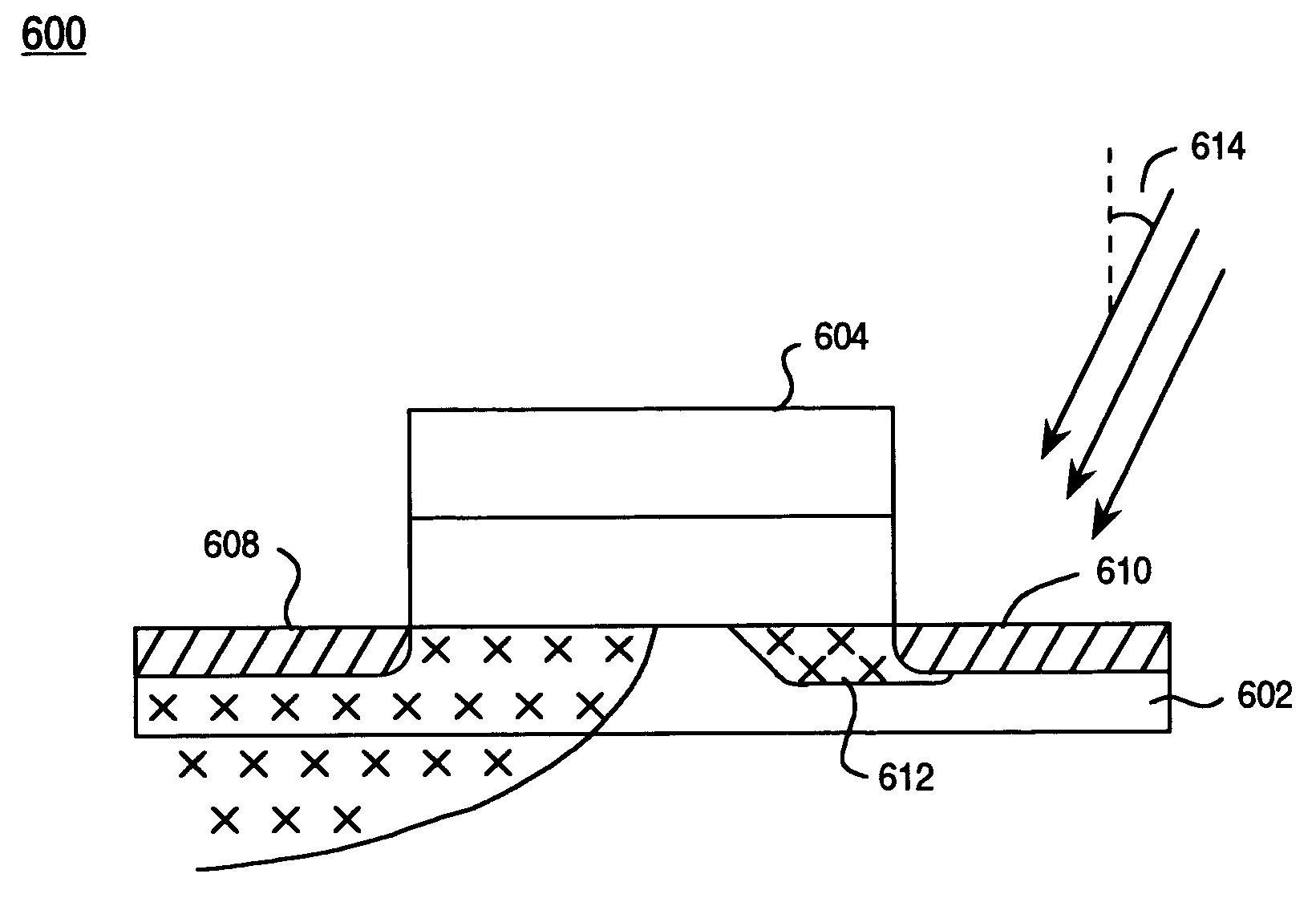
Embodiments of the present invention include a method for manufacturing a transistor comprising forming a gate conductor above a semiconductor substrate; forming a lightly doped implant region within the substrate, wherein the lightly doped implant region is substantially on the source side of the transistor; and forming a counter doping implant region within the substrate, wherein the counter-doping implant region is substantially on the drain side and wherein the counter-doping reduces the net channel impurity concentration on the drain side.

Description

FIELD OF THE INVENTION[0001]The present invention relates to the manufacture of an integrated circuit. More specifically, embodiments of the present invention relate to the formation of an n-channel and / or p-channel asymmetrical transistor using an arsenic drain side implantation to reduce DIBL.RELATED ART[0002]Moore's Law states that the number of semiconductor devices, (e.g., transistors), per unit area will double every 18–24 months. While other factors such as design improvements contribute to the rapid growth, one of the fundamental drivers of this inexorable density increase is the ever-shrinking minimum feature size of semiconductors. For example, a common minimum feature size of modern semiconductors is 0.15 microns.[0003]A modern integrated circuit, IC, for example a flash memory device, may have millions to hundreds of millions of devices made up of complex, multi-layered structures that are fabricated through hundreds of processing steps. Those structures, for example a g...

Claims


Application Information

Patent Timeline
Patent Type & Authority Patents(United States)
IPC IPC(8): H01L21/331
CPCH01L21/26586H01L29/7835H01L29/66659H01L29/1045
Inventor THURGATE, TIMOTHYWONG, NGA-CHING
Owner INFINEON TECH LLC
Learn More