Check patentability & draft patents in minutes with Patsnap Eureka AI!

Optical position encoder having alignment indicators providing quantitative alignment indications

a technology of optical position and indicator, applied in the direction of instruments, measuring devices, converting sensor output optically, etc., can solve the problem of substantial performance degradation

Inactive Publication Date: 2006-06-27
THE GSI GRP LLC
View PDF2 Cites 22 Cited by
  • Summary
  • Abstract
  • Description
  • Claims
  • Application Information

AI Technical Summary

Benefits of technology

[0005]In currently known methods of aligning optical encoders, such as the Lissajous-based method described above, there is little or no quantitative information provided to a user about the magnitude of misalignment. It is possible, for example, to achieve an acceptable Lissajous pattern at a position of marginal alignment, such that even a relatively minor perturbation of an assembled encoder may cause performance to degrade substantially. This marginal alignment can result in part because the Lissajous pattern is sensitive to aspects of the installed encoder other than alignment. It would be desirable to have an alignment technique that more directly reflects alignment per se, and that provides quantitative alignment information so as to enable an installer or other user to readily assess both the polarity (direction) and magnitude of any misalignment.

Problems solved by technology

It is possible, for example, to achieve an acceptable Lissajous pattern at a position of marginal alignment, such that even a relatively minor perturbation of an assembled encoder may cause performance to degrade substantially.

Method used


Image

  • Optical position encoder having alignment indicators providing quantitative alignment indications
  • Optical position encoder having alignment indicators providing quantitative alignment indications
  • Optical position encoder having alignment indicators providing quantitative alignment indications

Examples


Embodiment Construction

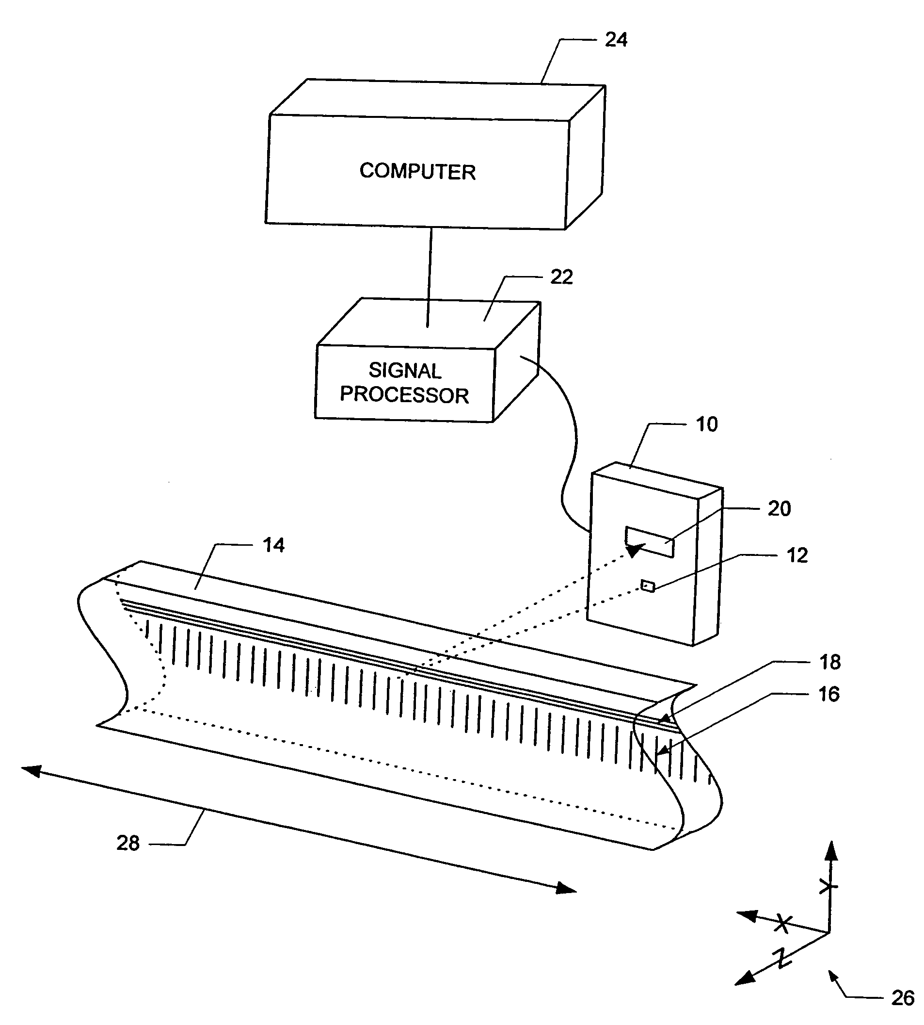
[0020]In FIG. 1, sensor apparatus 10 is installed as part of a reflective, diffractive optical encoder. A source 12 illuminates a scale 14 on which a periodic, reflective diffraction grating 16 is formed. The diffraction grating 16 is also referred to as the “main track”, as distinct from a “reference track”18 also formed on the scale. Light from the source 12 is reflectively diffracted from the scale 14 toward the sensor apparatus 10, which in the illustrated embodiment includes an optical detector 20. The diffraction grating 16 generates multiple orders of diffracted light which interfere with each other to form an optical fringe pattern (not illustrated) on the detector 20. The samples from the detector 20 are sent to a signal processor 22 which calculates a fringe phase for each sample. A computer 24 is coupled to the signal processor 20 for carrying out an alignment process as described below.

[0021]For ease of reference, a set of coordinate axes 26 are shown to indicate directi...


PUM


Abstract

An optical encoder includes an optical source, a scale, an optical detector and signal processing circuitry. The scale is operative with a light beam from the source to generate an optical pattern such as a line pattern extending in an X direction of relative movement between the scale and the source. The detector generates analog detector output signals indicative of the location of the optical pattern on the detector in an alignment direction orthogonal to the X direction. The detector may include two bi-cell elements spaced apart in the X direction, each element including two cells of complementary shape, such as a sharks-tooth. The signal processing circuitry operates in response to the detector output signals to generate an alignment value indicating a polarity and a magnitude of misalignment between the detector and the scale in the alignment direction. A method of providing information to a user regarding alignment of a detector and an encoder scale employs a graphical alignment indicator displayed on a computer display. The graphical alignment indicator has a bipolar indicator scale and a marker whose location on the scale is based on the alignment values such that the magnitude and polarity of misalignment is indicated.

Description

BACKGROUND OF THE INVENTION[0001]The present invention is related to the field of optical position encoders.[0002]Optical position encoders are often sold in an unassembled or “kit” form so as to be integrated into higher-level assemblies. In one common configuration, the optical encoder includes a scale, such as an elongated linear scale, that is to be placed on an item whose position is to be measured. The encoder also includes a sensor assembly that is to be mounted in a relatively stationary position immediately adjacent to the scale. The sensor assembly includes an optical source, such as a laser diode, and a photodetector. Light from the source is diffracted by a grating pattern on the scale and produces an interference pattern at the detector. Motion of the scale produces a corresponding apparent motion of the interference pattern which is detected by the detector. The detector output(s) are processed by electronic circuitry to convert the raw detector signals into a higher-l...

Claims


Application Information

Patent Timeline
Patent Type & Authority Patents(United States)
IPC IPC(8): G01D5/34
CPCG01D5/34707
Inventor MITCHELL, DONALD K.THORBURN, WILLIAM G.GOLDMAN, ANDREWHINRICHS, KEITH M.
Owner THE GSI GRP LLC
Features
  • R&D
  • Intellectual Property
  • Life Sciences
  • Materials
  • Tech Scout
  • Unparalleled Data Quality
  • Higher Quality Content
  • 60% Fewer Hallucinations
Learn More