
Fiber optic radiochromic dosimeter probe and method to make the same

a fiber optic and radiochromic technology, applied in the field of fiber optic radiochromic dosimeter probes, can solve the problems of errors, serious complications, and complex modern dose calculation and delivery techniques, and achieve the effect of accurate localization of radiation sensitive layers and safe use on patients

Active Publication Date: 2015-04-07
UNIV HEALTH NETWORK +1
View PDF67 Cites 2 Cited by
  • Summary
  • Abstract
  • Description
  • Claims
  • Application Information

AI Technical Summary

Benefits of technology

[0059]In one embodiment, the material of the reflector and the material of the optical fiber allow to maintain geometric integrity of MR images such that accurate localization of the radiation sensitive layer is possible on the MR images.
[0060]In one embodiment, the material of the reflector and the material of the optical fiber generate a minimum perturbation of the local field.
[0061]In one embodiment, the material of the reflector and the material of the optical fiber can be safely used on patients by limiting a length of conducting components such that it is insufficient to induce heating from the RF system.

Problems solved by technology

While the modern dose calculation and delivery techniques are becoming more complex, there is also a strong trend towards dose escalation, steeper dose gradients close to the tumor, and hypofractionation—aspects of treatment that can lead to serious complications if errors were made during delivery.
These errors can occur due to internal and external motion artifacts (i.e. patient movement, breathing, etc), dose calculation and human mistakes.
Unfortunately the reasons individual treatment monitoring is not currently performed as part of standard treatment are instrumentation and implementation complexity and expense.
Variables such as internal and external motion, patient placement, dose calculation inconsistencies and human error have been identified as causes of misdelivery of the ideal planned treatment.
However, implementing this step on every patient with the current commercially available tools is complex and expensive.
This is complicated further by the growing field of MR-guided radiotherapy and MR-guided brachytherapy (MRgRT) which requires MR-compatible QA tools.
For diodes this issue can create as much as a 30% error to local dose distribution due to their size, density and composition.
This complicates and prolongs work-flow and may yield incorrect results.

Method used


Image

  • Fiber optic radiochromic dosimeter probe and method to make the same
  • Fiber optic radiochromic dosimeter probe and method to make the same
  • Fiber optic radiochromic dosimeter probe and method to make the same

Examples


example 1

[0146]An example of a fabrication process for the dosimeter probe is as follows. A radiochromic thin film was spin coated on a 3M Vikuiti™ ESR mirror using a Solitec spin coater. The ESR mirror being flexible, a piece of about 25 mm by 25 mm was affixed on a glass substrate to avoid any deformation due to the vacuum that holds the substrate in place during the spinning. The quantity of radiochromic fluid used was 150 μl, and the rotation speed was set to 730 rpm for the duration of 11 seconds, yielding an average thickness of the desired 15 μm. A ESKA® acrylic fiber developed and manufactured by Mitsubishi was used. The core diameter was 486 μm, the fiber diameter was 500 μm and the numerical aperture was 0.51. The unjacketed plastic optical fiber (POF) was cut to 1.05 m length to ensure the final length is 1 m. One end of the plastic fiber was connectorized with a SMA connector. On the probe side, the plastic fiber was polished. If necessary, an ultrasound bath was used to clean th...

example 2

[0148]A real-time fiber optic dosimeter probe was fabricated by spin coating, to a 8.5 μm thickness of a radiochromic radiation sensitive material on a dielectric mirror. The material was then cut as a slice of about 2 cm long and 500 μm wide. A 1 mm long poly(methyl methacrylate) capillary having an outer diameter of 1 mm and an inner diameter of 500 μm was cut 1 cm long. A 500 μm side hole was drilled through the capillary near the center; the capillary was held in a fiber optics holder and the radiation sensitive slice was slipped through the capillary side hole. Two polished ends of 500 μm plastic multimode optical fibers were inserted in both ends of the capillary and firmly pressed on the radiochromic coated mirror. Small drops of a cyano-acrylate adhesive were used to affix both fibers at the capillary ends. A low viscosity epoxy adhesive was finally prepared and injected in the side holes of each probe to affix the radiochromic element on the optical fibers and match the ref...

example 3

[0150]A real-time fiber optic dosimeter probe was fabricated by depositing a 1.7 μm thick radiochromic thin film on a dielectric mirror that was afterwards assembled on a fiber tip. A protective coating covered the assembled probe. The outside diameter of the plastic optical fiber was 500 μm. The fiber optic dosimeter probe was irradiated at a dose rate of 500 cGy / minute to a total dose of 5 Gy. Absorbance spectra of the fiber optic radiochromic dosimeter probe were measured before and after irradiation as shown in FIG. 5. After irradiation, the absorbance increased in the 585 nm and 636 nm bands. The real-time measurement of the optical density (OD) change, before, during, and after irradiation at 500 cGy / minute to 500 cGy is shown in FIG. 6, demonstrating that the optical dosimeter probe using radiochromic thin film at the tip is real-time sensitive.

[0151]Absorbance spectra acquired before and after irradiation of the fiber optic dosimeter probe demonstrate principle functionality...


PUM

PropertyMeasurementUnit
thicknessaaaaaaaaaa
thicknessaaaaaaaaaa
thicknessaaaaaaaaaa

Abstract

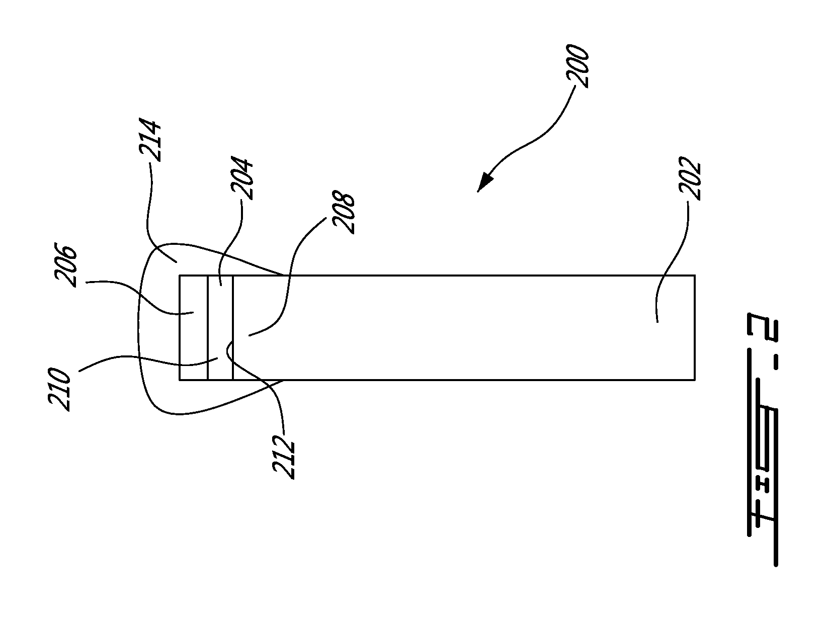
A fiber optic dosimeter probe for sensing radiation dose including an optical fiber having a free end and a sensitive end, a window having a sensitive side and a rear side; a radiation sensitive layer between the sensitive end of the optical fiber and a sensitive side of the window, the radiation sensitive layer being made of a material having an optical property that changes with absorbed radiation dose, an amount of the material corresponding to a predetermined sensitivity to radiation; wherein the window and the optical fiber have a near water equivalent interaction with radiation and are MR compatible.

Description

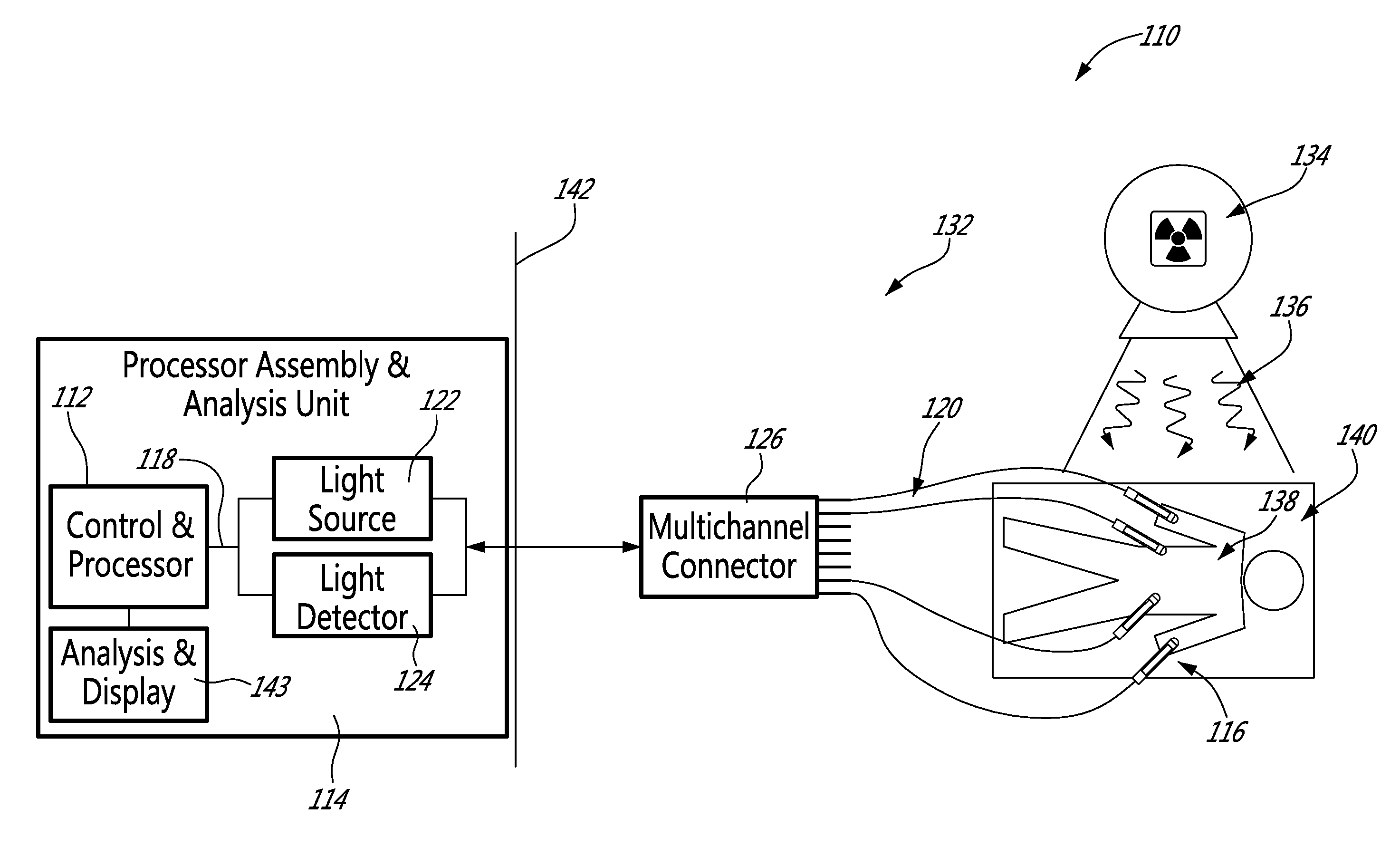
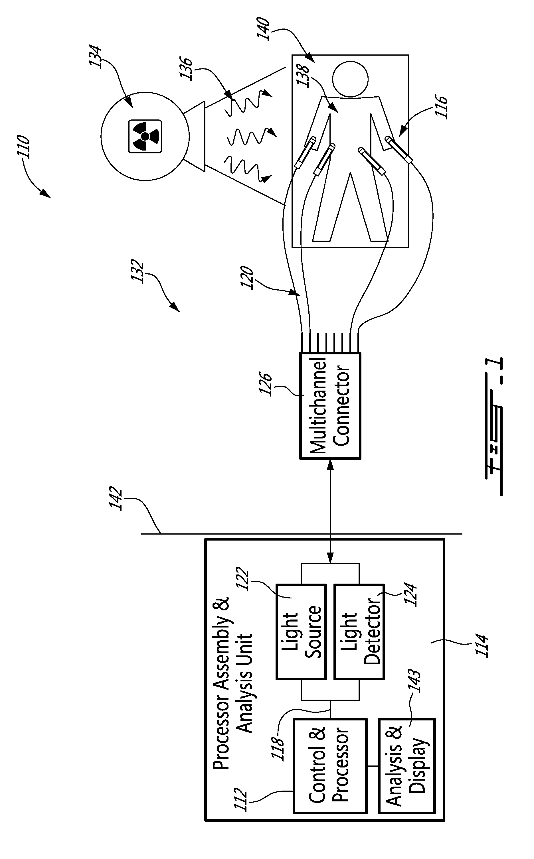
CROSS-REFERENCE TO RELATED APPLICATIONS[0001]The present application is a national phase entry of PCT Application No. PCT / IB2011 / 053006, entitled “FIBER OPTIC RADIOCHROMIC DOSIMETER PROBE AND METHOD TO MAKE THE SAME” filed Jul. 6, 2011; which in turn claims priority of U.S. provisional patent application No. 61 / 362,082 filed Jul. 7, 2010, the specifications of which are hereby incorporated by reference.TECHNICAL FIELD[0002]The invention relates to dosimeters for radiotherapy and more specifically to a fiber optic radiochromic dosimeter probe.BACKGROUND OF THE ART[0003]Scientists at University Health Network have recently developed an in-vivo optical dosimeter platform used for the real-time monitoring of radiation dose delivered to clinical radiotherapy patients. Their dosimeter platform is described in U.S. Pat. No. 7,399,977. It enables radiotherapy techniques such as MR-guided Radiotherapy (MRgRT) and MR-guided brachytherapy and imminent quality assurance requirements for the fie...

Claims


Application Information

Patent Timeline
Patent Type & Authority Patents(United States)
IPC IPC(8): G01T1/06G01T1/20
CPCG01T1/06G01T1/201Y10T29/49826G01T1/04
Inventor RINK, ALEXANDRAJAFFRAY, DAVIDMERMUT, OZZYCARON, SERGECROTEAU, ANDREROY-MOISAN, FRANCOIS
Owner UNIV HEALTH NETWORK
Learn More