Microfluidic device

a microfluidic device and microfluidic technology, applied in the field of microfluidic devices, can solve the problems of difficult to achieve a good level of control, difficult to systematically generate all possible droplet pairs, and strict limitations of the maximum flow rate and hence throughput of the negative pressure driven system. , to achieve the effect of short switching times

Active Publication Date: 2017-11-07
EURO LAB FUER MOLEKULARBIOLOGIE EMBL
View PDF25 Cites 2 Cited by
  • Summary
  • Abstract
  • Description
  • Claims
  • Application Information

AI Technical Summary

Benefits of technology

[0009]In one aspect the apparatus comprises the substance liquid channel network and the separation liquid channel are connected to the droplet channel through a droplet generation junction, and wherein the substance liquid channel network comprises a first substance liquid inlet, at least one second substance liquid inlet and at least one substance liquid combining area. The use of substance liquid combining area has the advantage that the substance can be brought together in a defined and controlled manner and the substance concentrations of the first substance and at least of the second substance can be controlled. It is also possible to combine or mix more than two substances and the number of substances is only limited by the number of substance inlets ending in the substance liquid combining area. Only one single junction may be used for generating all droplets in the corresponding droplet channel. Droplet fusion is not necessary and can be omitted as the substances are combined prior to droplet formation.
[0013]In an aspect, the apparatus comprises a separation liquid channel, a droplet channel, and a substance liquid channel network wherein the substance liquid channel network and the separation liquid channel are connected to the droplet channel by a droplet generation junction. The substance liquid channel network comprises at least one first substance liquid inlet, at least one first valve and at least one pressure device for applying a continuous pressure or a continuous flow to the at least one first substance liquid at the at least one first substance liquid inlet. The at least one first valve is switchable between a first position in which a liquid connection to the droplet generation junction is open and a second position in which the liquid connection to the droplet generation junction is closed. Applying a continuous pressure or a continuous flow to the inlet has the advantage that shorter switching times and minimal perturbations occur in the system. In addition, the size distribution of the droplets is more homogeneous and the mixing or combination of substance liquids is better defined and controlled.
[0021]The apparatus may comprise a first substance liquid drain, and the substance liquid drain may be closed in the first position and may be open in the second position. This ensures that at least one way for the substance liquid is open at any time. A constant flow can thus be applied to the substance liquid inlet allowing short switching times between the inlets.

Problems solved by technology

While in theory this approach allows for the generation of many mixtures of different compounds (that can be screened for a desired effect or exploited for on-chip synthesis of compound libraries) the system has several limitations: The system is dependent on droplet fusion and only allows for the generation of combinatorial droplet pairs; The system is driven by negative pressure.
All flow is generated by aspirating from the outlet resulting in different droplet sizes for the different compounds when applying constant valve opening times. Even though this can be compensated in theory by adjusting the individual valve opening times, only a poor level of control can be achieved.
Since each infused compound needs a specific valve opening time, it seems very challenging to systematically generate all possible droplet pairs (and synchronize the generation of the individual droplets to allow for pairing).
Furthermore, a negative pressure driven system has strict limitations in terms of the maximum flow rates and hence the throughput.

Method used


Image

  • Microfluidic device
  • Microfluidic device
  • Microfluidic device

Examples


example 1

Differentiation

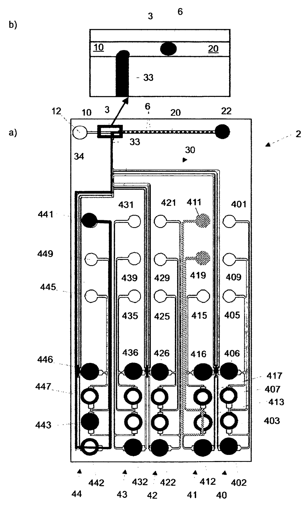
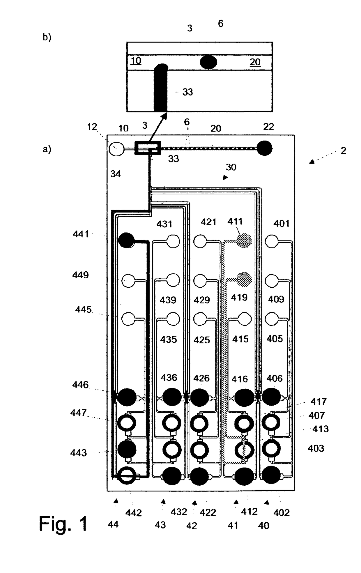
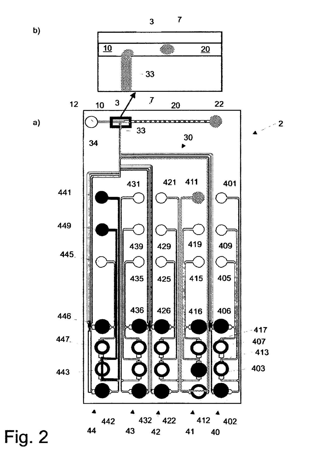
[0058]The microfluidic apparatus 2 is used to screen media ingredients (e.g. growth factors and chemical stimuli) triggering the differentiation of stem cells into specific lineages (e.g. neurons, muscle cells, etc.). It is well known that the differentiation of stem cells is dependent on many (chemical) factors in parallel. Hence screening combinatorial mixtures of media ingredients is required and even commercially exploited in conventional systems (e.g. plasticell). While a conventional setup requires large amounts of stem cells and only allows for relatively low throughput, the microfluidic apparatus 2 of the present disclosure can circumvent these limitations.

[0059]In this example, a suspension of stem cells as well as a number of growth factors and chemical stimuli are continuously injected into (different inlets of) the microfluidic apparatus 2. Using a predefined sequence of valve configurations, all possible combinations of growth factors and chemical stimuli...

example 2

rial Chemistry

[0064]The novel microfluidic apparatus 2 is used to set up samples containing different reactants for the combinatorial synthesis of bioactive molecules. For example, the microfluidic apparatus 2 can be used to mix azides and alkenes for “click chemistry” reactions (e.g. Huisgen 1,3-Dipolar Cycloaddition) in a combinatorial fashion. In this approach, a number of alkenes (n) and a number of azides (z) are continuously injected into the microfluidic apparatus 2. Using a predefined sequence of valve configurations, all possible alkeneazide pairs are co-encapsulated into the product droplets 6. Downstream of the encapsulation step, the product droplets 6 are incubated at elevated temperature for a time period sufficient to obtain the products of the chemical reactions.

[0065]Subsequently, the product droplets 6 are mixed with assay reagents to test for biological activity of the newly generated products. For this purpose, the product droplets 6 are fused with droplets conta...

example 3

Potent Drug Combinations

[0067]Many diseases cannot be cured based on the application of a single drug acting on a single drug target. For example, HIV infections are usually treated using highly active antiretroviral therapy (HAART). In this approach, drug cocktails targeting different viral proteins (e.g. Reverse Transcriptase, HIV protease or the Envelope protein) are administered at the same time to avoid the generation of resistant mutants. Similarly, the treatment of cancer or multi-resistant bacteria often involves the application of drug cocktails.

[0068]The microfluidic apparatus 2 of the present disclosure can be used to systematically encapsulate all possible combinations of a given number of drugs into droplets and monitor their potentially cumulative effects on a co-encapsulated pathogen (also infused through one of the inlets of the device). After the sample generation and an incubation time allowing the pathogen to proliferate, the product droplets 7 and their contents ...


PUM

PropertyMeasurementUnit
polydispersityaaaaaaaaaa
heightaaaaaaaaaa
widthaaaaaaaaaa

Abstract

The present disclosure teaches an apparatus and a method for providing one or more substance liquids to a microfluidic channel network (30). The microfluidic apparatus includes valves for switching the one or more substance liquids to a microfluidic channel network (30). The apparatus can be used to generate a sequence of the one or more substance liquids as individual droplets in an immiscible separation liquid wherein individual ones of the sequence of droplets are located between the separation liquid.

Description

[0001]The present disclosure relates to a microfluidic apparatus and a method for generating a sequence of substances in a microfluidic channel. The present disclosure relates in particular to a microfluidic apparatus and a method for generating a sequence of encapsulated droplets in a microfluidic channel.INTRODUCTION AND RELATED ART[0002]Microfluidic devices have shown great potential for many therapeutic, diagnostic, chemical or biochemical applications. They enable work with a minimized amount of substances. One aspect in microfluidics is the control of flows through a channel network. Various techniques have been established to generate and operate microfluidic valves. For example, multilayer soft lithography can be used to fabricate orthogonal channels in two different layers.[0003]Piezo electric acceptors push small pins into the chip made of flexible polymers, thus compressing the channel and stopping the flow within. So far, microfluidic valves have been used mainly to gene...

Claims


Application Information

Patent Timeline
Patent Type & Authority Patents(United States)
IPC IPC(8): G01N1/28B01L3/00G01J3/46
CPCG01N1/28B01L3/502784G01J3/46B01L2200/026B01L2200/061B01L2200/0673Y10T137/877B01L2300/0816B01L2400/0481B01L2400/0487G01J2003/466Y10T137/0318Y10T137/469B01L2200/0694
Inventor MERTEN, CHRISTOPHUTHARALA, RAMESH
Owner EURO LAB FUER MOLEKULARBIOLOGIE EMBL
Why Eureka
Try Eureka