
Conductive memory device with conductive oxide electrodes

a technology of conductive oxide and memory device, which is applied in the field of computer memory, can solve the problems of resistance-changing properties of certain cmos, which have not yet been implemented in a commercial memory product,

Inactive Publication Date: 2006-06-27
UNITY SEMICON
View PDF15 Cites 144 Cited by
  • Summary
  • Abstract
  • Description
  • Claims
  • Application Information

AI Technical Summary

Problems solved by technology

However, the materials described in the U.S. Pat. No. 6,204,139 patent are not generally applicable to RAM memory because the resistance of the material, when scaled to small dimensions, is considered to be too large to make a memory with fast access times.
The discovery of the resistance-changing property of certain CMOs, however, is relatively recent and has not yet been implemented in a commercial memory product.

Method used


Image

  • Conductive memory device with conductive oxide electrodes
  • Conductive memory device with conductive oxide electrodes
  • Conductive memory device with conductive oxide electrodes

Examples


Embodiment Construction

[0028]In the following description, numerous specific details are set forth to provide a thorough understanding of the present invention. It will be apparent, however, to one skilled in the art that the present invention may be practiced without some or all of these specific details. In other instances, well known process steps have not been described in detail in order to avoid unnecessarily obscuring the present invention.

Overview

[0029]An electrode, according to The American Heritage® Dictionary of the English Language, is typically nothing more than solid electric conductor through which an electric current enters or leaves an electrolytic cell or other medium. Its only function is to make electrical contact with a circuit component.

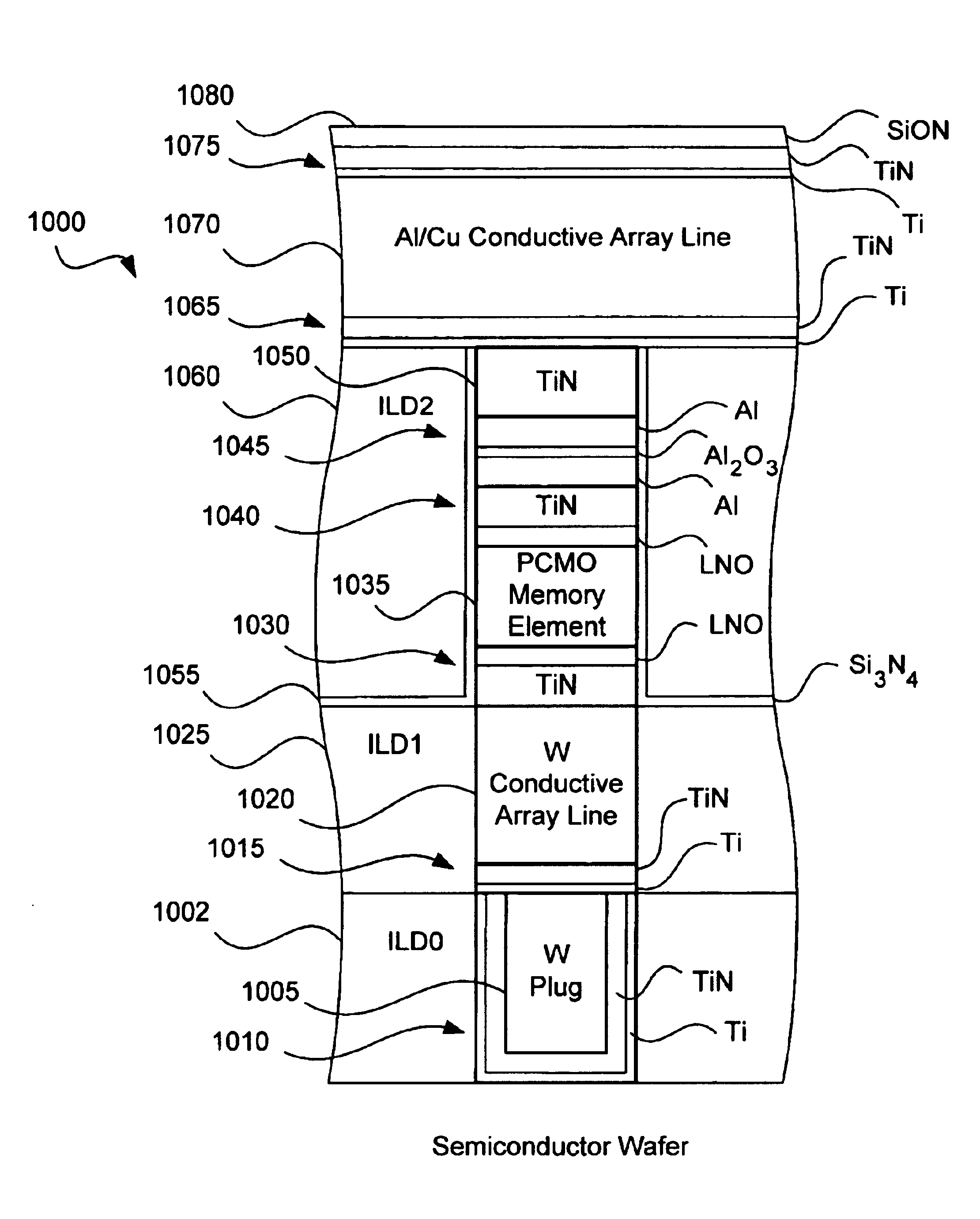
[0030]However, such a narrow view of electrodes is unnecessary. If certain materials are used as electrodes, the electrodes can be used for multiple purposes. Oxides and nitrides are especially well suited for acting as a barrier layer, adhesion layer...


PUM


Abstract

A multi-resistive state element that uses barrier electrodes is provided. If certain materials are used as electrodes, the electrodes can be used for multiple purposes. Oxides and nitrides are especially well suited for acting as a barrier layer, and possibly even an adhesion layer and a sacrificial layer.

Description

CROSS-REFERENCE TO RELATED APPLICATIONS[0001]This application is a continuation-in-part of U.S. patent application Ser. No. 10 / 330,512, filed Dec. 26, 2002 now U.S. Pat. No. 6,753,561, which claims the benefit of U.S. Provisional Application No. 60 / 400,849, filed Aug. 2, 2002, U.S. Provisional Application No. 60 / 422,922, filed Oct. 31, 2002, and U.S. Provisional Application 60 / 424,083, filed Nov. 5, 2002, all of which are incorporated herein by reference in their entireties and for all purposes. This application is related to the following U.S. patent applications: application Ser. No. 10 / 360,005, filed Feb. 7, 2003, now U.S. Pat. No. 6,917,539; application Ser. No. 10 / 330,153, filed Dec. 26, 2002, now U.S. Pat. No. 6,834,008; application Ser. No. 10 / 330,964, filed Dec. 26, 2002, now U.S. Pat. No. 6,831,854; application Ser. No. 10 / 330,170, filed Dec. 26, 2002; application Ser. No. 10 / 330,900, now U.S. Pat. No. 6,850,429, filed Dec. 26, 2002; application Ser. No. 10 / 330,150, filed D...

Claims


Application Information

Patent Timeline
IPC IPC(8): H01L31/062G11C11/56G11C13/00H01L27/24
CPCG11C11/5685H01L45/165G11C13/003H01L27/24H01L27/2418H01L27/2436H01L45/08H01L45/1233H01L45/1253H01L45/147G11C13/0007G11C2213/31G11C2213/72G11C2213/74G11C2213/76G11C2213/77H10B63/22H10B63/30H10N70/24H10N70/826H10N70/841H10N70/8836H10N70/043H10B63/00
Inventor RINERSON, DARRELLLONGCOR, STEVEN W.HSIA, STEVE KUO-RENKINNEY, WAYNEWARD, EDMOND R.CHEVALLIER, CHRISTOPHE J.
Owner UNITY SEMICON
Learn More