Methods for the reduction and elimination of particulate contamination with CVD of amorphous carbon

a technology of amorphous carbon and cvd, which is applied in the field of manufacturing integrated circuits, can solve the problems of easy stripping and increase of particle contamination, and achieve the effects of reducing particle contamination, reducing particle contamination, and reducing particle contamination

Inactive Publication Date: 2006-01-19
APPLIED MATERIALS INC +1
View PDF16 Cites 391 Cited by
  • Summary
  • Abstract
  • Description
  • Claims
  • Application Information

AI Technical Summary

Benefits of technology

[0011] Aspects of the invention generally provide a method for forming a material layer, such as an amorphous carbon layer, deposited on a dielectric material such as oxide, nitride, silicon carbide, carbon doped oxide, etc., or a metal layer such as tungsten, aluminum or poly-silicon with minimal defect formation and particle contamination. In one aspect, a method for processing a substrate in a chamber is provided. The method includes depositing a first material inside the chamber for a first deposition time, then positioning a substrate inside the chamber, and providing a gas mixture by flowing one or more hydrocarbon compounds and an inert gas to the deposition chamber. The method further includes applying an electric field to the gas mixture and heating the gas mixture to thermally decompose the one or more hydrocarbon compounds in the gas mixture and generate a plasma, and depositing a second material on the substrate for a second deposition time. Further, at least one gas flow of the one or more hydrocarbon compounds is terminated while still flowing the inert gas to the deposition chamber for a first time period and any gas or plasma generated is pumped out of the chamber for a second time period to reduce particle contamination on the substrate.
[0012] In another aspect of the invention, a method for processing a substrate includes positioning a substrate inside the chamber, providing a gas mixture by flowing one or more hydrocarbon compounds and an inert gas to the deposition chamber, applying an electric field to the gas mixture and heating the gas mixture to thermally decompose the one or more hydrocarbon compounds in the gas mixture and generate a plasma, and depositing a material on the substrate for a deposition time. The method further includes movi

Problems solved by technology

In addition, it is easily stripped away after pattern transfer.
This is a problem when low temperature deposition is required to be suit

Method used


Image

  • Methods for the reduction and elimination of particulate contamination with CVD of amorphous carbon
  • Methods for the reduction and elimination of particulate contamination with CVD of amorphous carbon
  • Methods for the reduction and elimination of particulate contamination with CVD of amorphous carbon

Examples


example 1

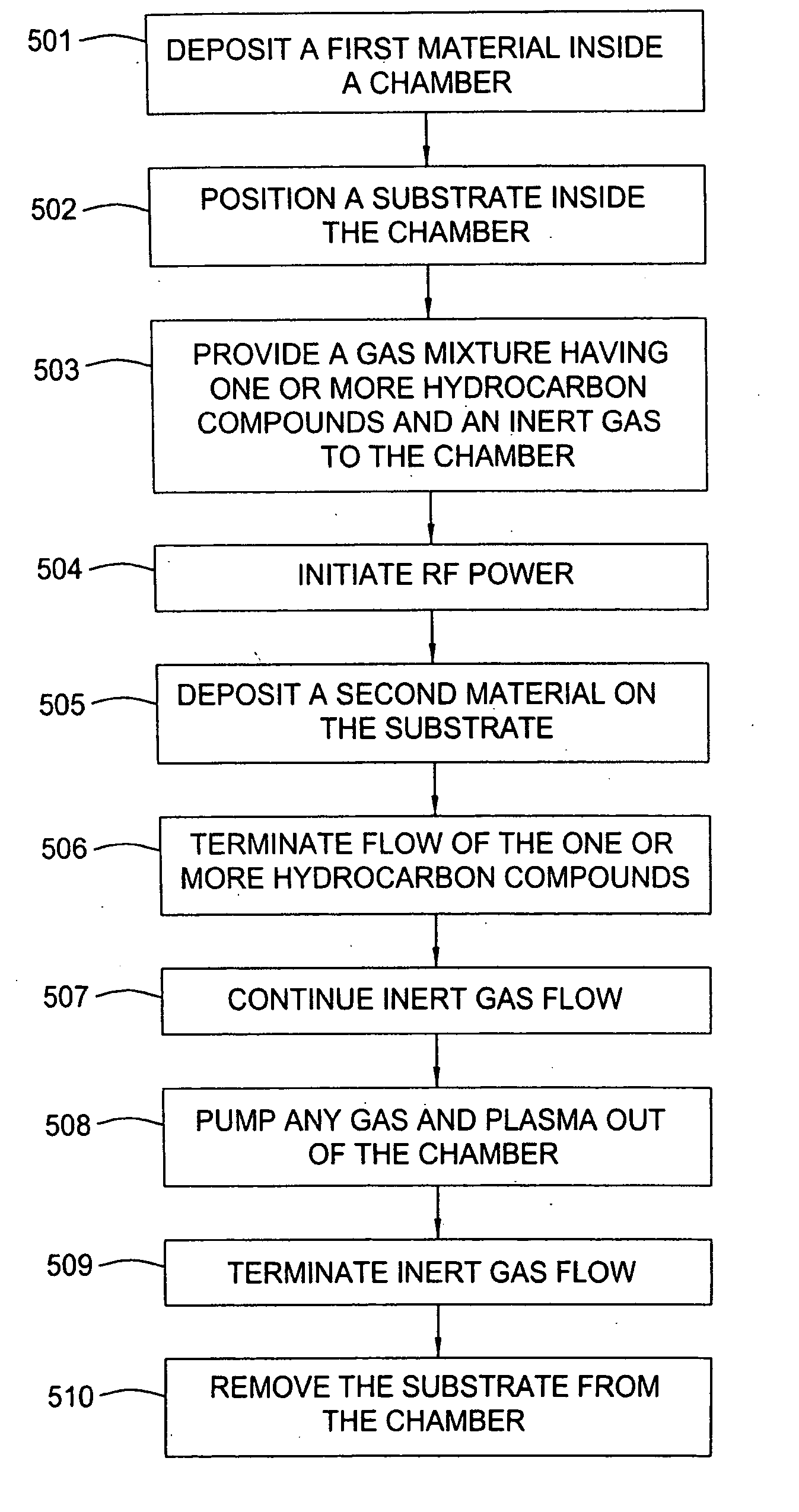
[0080] The chamber was pre-cleaned with an in-situ oxygen plasma by supplying an oxygen gas and initiating a RF power. A carbon film was then deposited inside the chamber at about 400° C. for a time period of 0, 5, 7, 10, 20, 30 seconds, or longer. This film is also called seasoning film. A substrate is loaded onto the substrate support of the chamber and an amorphous carbon layer was deposited on the substrate from a gas mixture of propylene and helium, having a chamber pressure of about 5.75 Torr and a substrate temperature of about 400° C. The substrate was positioned 250 mils from the gas distribution manifold, and RF power of 2.5 W / cm2 (1600 W) at a frequency of 13.56 MHz was applied to the manifold. The gas mixture described above was introduced into the chamber before the initiation of RF power. After the amorphous carbon layer was deposited on the substrate, the RF power and flow of the gas mixture were terminated. The chamber slit valve was opened to allow the gas mixture t...

example 2

[0082] Another example includes deposition of a carbon film at about 400° C. for a time period of about 10 seconds. The substrate was then introduced into the chamber and positioned 250 mils from the gas distribution system. A gas mixture of propylene and helium was introduced into the chamber before the initiation of RF power and an amorphous carbon layer was deposited on a substrate at a substrate temperature of about 400° C. After the amorphous carbon layer was deposited on the substrate, the RF power and flow of the gas mixture were terminated. The substrate was then positioned 1300 mils from the gas distribution system, while maintaining the chamber pressure. The chamber slit valve was opened to allow the gas mixture and / or plasma to be pumped out of the chamber. The numbers of the particles on the substrate were measured to see the effect of the position of the substrate from the gas distribution system on particle contamination.

[0083] The results are shown in FIG. 10, which ...

example 3

[0084] Still another example includes pre-cleaning the chamber with an in-situ oxygen plasma by supplying an oxygen gas and initiating a RF power. No carbon film was deposited before an amorphous carbon layer was deposited on a substrate from a gas mixture of propylene and helium at a substrate temperature of about 400° C. and RF power of 1600 W) at a frequency of 13.56 MHz applied to the gas distribution system. The flow of propylene was terminated while the flow of helium is still on for about 20 seconds. The substrate was positioned at about 250 mils from the gas distribution system. The chamber slit valve was opened to allow the gas mixture to be pumped out of the chamber. The numbers of the particles on the substrate were measured to see the effect of purging particles out of the chamber by the inert helium gas flow on particle contamination.

[0085] The results are shown in FIG. 12, which demonstrate that without maintaining the inert helium gas, particles more than about 0.12 ...


PUM

PropertyMeasurementUnit
Temperatureaaaaaaaaaa
Timeaaaaaaaaaa

Abstract

A method is provided for forming an amorphous carbon layer, deposited on a dielectric material such as oxide, nitride, silicon carbide, carbon doped oxide, etc., or a metal layer such as tungsten, aluminum or poly-silicon. The method includes the use of chamber seasoning, variable thickness of seasoning film, wider spacing, variable process gas flows, post-deposition purge with inert gas, and post-deposition plasma purge, among others, to make the deposition of an amorphous carbon film at low deposition temperatures possible without any defects or particle contamination.

Description

BACKGROUND OF THE DISCLOSURE [0001] 1. Field of the Invention [0002] The invention relates to the fabrication of integrated circuits and to a method for depositing a layer on a substrate and the structures formed by the layer. [0003] 2. Description of the Related Art [0004] In the manufacture of integrated circuits, chemical vapor deposition processes are often used for deposition or etching of various material layers. Conventional thermal CVD processes supply reactive compounds to the substrate surface where heat-induced chemical reactions take place to produce a desired layer. Plasma enhanced chemical vapor deposition (PECVD) processes employ a power source (e.g., radio frequency (RF) power or microwave power) coupled to a deposition chamber to increase dissociation of the reactive compounds. Thus, PECVD processes allow deposition to be achieved at lower temperatures than those required for analogous thermal processes. This is advantageous for processes with stringent thermal budg...

Claims


Application Information

Patent Timeline
IPC IPC(8): H01L21/469
CPCC23C16/26C23C16/4401H01L21/3146C23C16/4405C23C16/4404H01L21/02274H01L21/02115H01L21/02271
Inventor SEAMONS, MARTIN JAYYEH, WENDY H.RATHI, SUDHA S. R.BOTELHO, HERALDO L.
Owner APPLIED MATERIALS INC
Why Eureka
Try Eureka