Electrostatic chuck component and plasma device provided with same

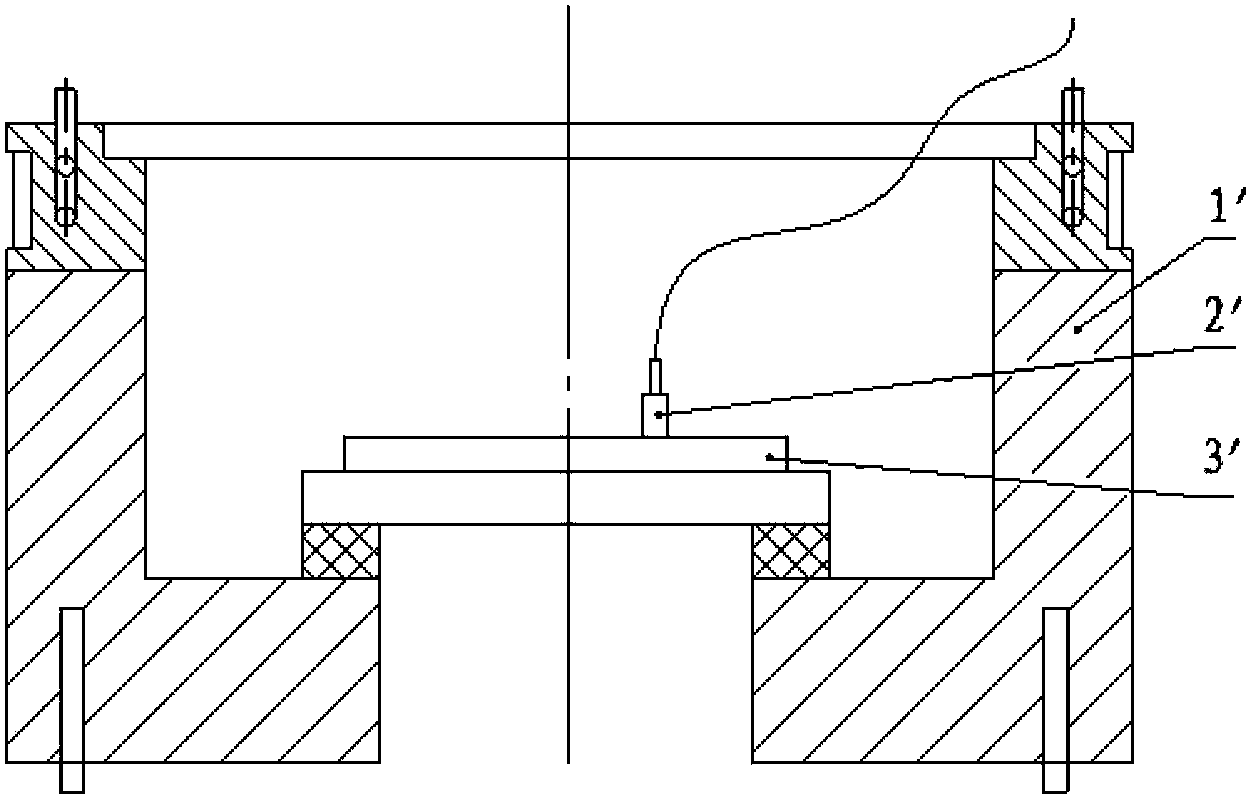
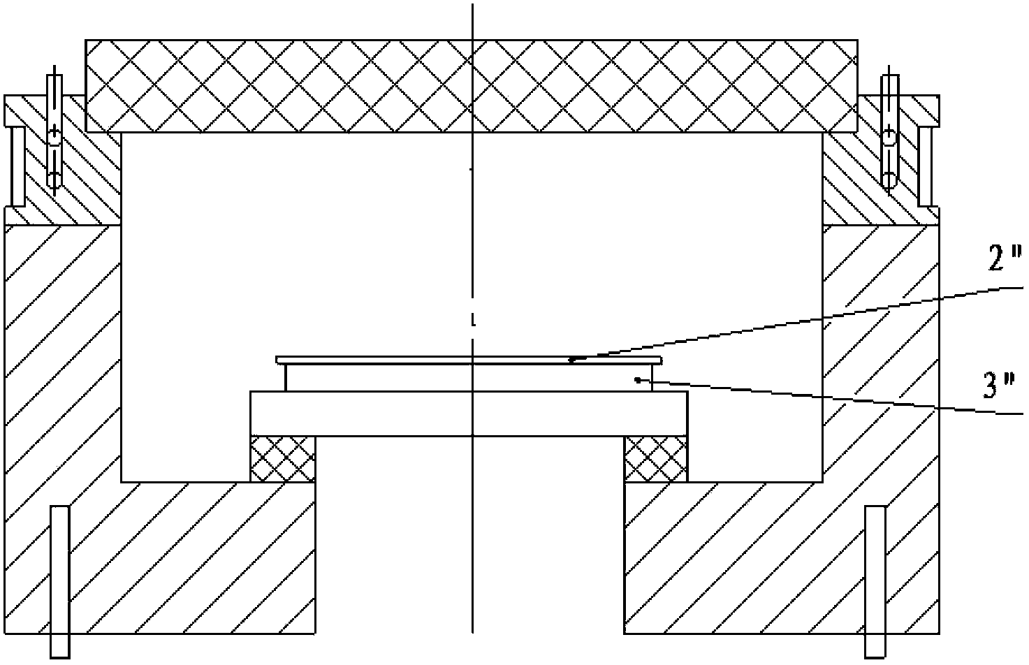
A technology for electrostatic chucks and components, applied to electrical components, circuits, discharge tubes, etc., can solve problems such as damage to TCWafer2", affect the life of electrostatic chuck 3', damage the disk surface, etc., to improve accuracy and repeatability, test The temperature process is simple and easy, and the effect of reducing the cost of use

Active Publication Date: 2014-01-29
BEIJING NAURA MICROELECTRONICS EQUIP CO LTD
View PDF4 Cites 6 Cited by
  • Summary
  • Abstract
  • Description
  • Claims
  • Application Information

AI Technical Summary

Problems solved by technology

[0006] However, the above-mentioned temperature measurement method using the surface temperature gauge 2' has the following four disadvantages: 1) The surface thermometer 2' must be in contact with the electrostatic chuck 3' to realize the temperature measurement function, and the probe of the surface thermometer 2' is relatively hard , the disk surface of the electrostatic chuck 3' must be damaged during the measurement project, which seriously affects the life of the electrostatic chuck 3'; The surface of the chuck 3' caused the particles to seriously exceed the standard during the process; 3) The surface thermometer 2' is generally operated by hand, and the force of pressing the surface thermometer 2' by different operators is different, resulting in different readings of the thermometer. The vibration of the operator will also cause the difference in the reading of the thermometer 2', so tha

Method used


Image

  • Electrostatic chuck component and plasma device provided with same
  • Electrostatic chuck component and plasma device provided with same
  • Electrostatic chuck component and plasma device provided with same

Examples


Example Embodiment

[0034] The embodiments of the present invention are described in detail below. Examples of the embodiments are shown in the accompanying drawings, in which the same or similar reference numerals indicate the same or similar elements or elements with the same or similar functions. The embodiments described below with reference to the accompanying drawings are exemplary, and are intended to explain the present invention, but should not be construed as limiting the present invention.

[0035] In the description of the present invention, it should be understood that the terms "center", "longitudinal", "transverse", "length", "width", "thickness", "upper", "lower", "front", " The orientation or positional relationship indicated by “rear”, “left”, “right”, “vertical”, “horizontal”, “top”, “bottom”, “inner”, “clockwise”, and “counterclockwise” are based on the attached The orientation or positional relationship shown in the figure is only for the convenience of describing the present in...


PUM


Abstract

The invention discloses an electrostatic chuck component. The electrostatic chuck component comprises an electrostatic chuck, a fixing frame and a temperature sensor. The fixing frame is mounted on the electrostatic chuck. The temperature sensor is arranged on the fixing frame and opposite to the upper surface of the electrostatic chuck, and the lower end face of the temperature sensor is at a preset distance with the upper surface of the electrostatic chuck. According to the electrostatic chuck component and by means of a non-contact temperature measuring method, the lower end face of the temperature sensor is spaced from the upper surface of the electrostatic chuck, particle pollution produced during temperature measuring is decreased, secondary pollution to the electrostatic chuck is avoided, and service life of the electrostatic chuck is prolonged; meanwhile, compared with a temperature measuring mode by a conventional handheld temperature gauge, the non-contact temperature measuring method has the advantages that the temperature sensor is fixed through the fixing frame, measuring error produced by handheld operation of an operator is avoided, and temperature measuring accuracy of the temperature sensor is improved. The invention further discloses a plasma device provided with the above electrostatic chuck component.

Description

technical field [0001] The invention relates to the field of semiconductor equipment manufacturing, in particular to an electrostatic chuck assembly and a plasma device with it. Background technique [0002] Plasma devices are widely used in the manufacturing process of integrated circuits or MEMS devices. One notable application is the Inductive Coupled Plasma (ICP) device. Plasma contains a large number of active particles such as electrons, ions, excited atoms, molecules and free radicals. These active particles interact with the substrate to cause various physical and chemical reactions on the material surface, thereby changing the properties of the material surface. Plasma devices can complete a variety of processes in semiconductor manufacturing, such as anisotropic, isotropic etching, and chemical vapor deposition (Chemical Vapor Deposition, CVD). In the fabrication of semiconductor based devices, multiple layers of material may be alternately deposited onto and etc...

Claims


Application Information

Patent Timeline
IPC IPC(8): H01L21/683H01J37/32H01L21/67
CPCH01L21/6833H01L21/67248
Inventor 彭宇霖
Owner BEIJING NAURA MICROELECTRONICS EQUIP CO LTD
Why Eureka
Try Eureka