Method of reducing particle contamination for ion implanters

a technology of particle contamination and ion beam, which is applied in the field of particle contamination reduction methods for ion beam control circuits, can solve the problems of additional particles to be generated, and achieve the effects of minimizing particle contamination, minimizing particle contamination, and reducing the duty factor of ion beams

Active Publication Date: 2008-07-03
AXCELIS TECHNOLOGIES
View PDF14 Cites 9 Cited by
  • Summary
  • Abstract
  • Description
  • Claims
  • Application Information

AI Technical Summary

Benefits of technology

[0007]The present invention is directed to a circuit and method for reducing particle contamination that may be produced by beam strikes with electrodes and walls associated with the ion source and any other elements along the beamline of an ion implantation system. Also, more beam strikes make the wall surfaces more frangible which may cause additional particles to be generated by subsequent beam strikes. By reducing the beam duty or duration of such beam strikes, contaminate generation is also reduced. Several beam control or switch control circuits are disclosed that incorporate a high voltage high speed (HVHS) switch added in series between a high voltage supply and its respective electrode. For example, one or more of a suppression, extraction, cathode, or arc voltage supply and a respective electrode associated with the ion source may be switched by the HVHS switches to initiate or terminate the ion beam and reduce the beam ON-time or beam duty, thereby reducing the level of contaminates produced as a result of beam strikes.
[0008]The beam control circuit of the present invention comprises a high voltage switch connected in series with a power supply and an element associated with an ion source portion of the ion implantation system, wherein the switch is operable to interrupt or reestablish a connection between the power supply and the electrode. The beam control circuit also comprises a switch controller operable to control the duty factor or duty cycle of a beam produced within the ion implantation system by controlling the switch to close minimally before the start of ion implantation and to open minimally after completion of the implantation, thereby minimizing particle contamination. The beam control technique may be applied to wafer doping implantation and duty factor reduction.
[0024]In accordance with one or more other aspects of the present invention, a beam control circuit for minimizing particle contamination in an ion implantation system is also disclosed comprising an ion source for producing a quantity of ions which can be extracted in the form of an ion beam, and a high-voltage switch connected in series with a power supply and electrode associated with the ion source portion of the ion implantation system, operable to interrupt or reestablish a connection between the power supply and the electrode. The system further comprises a switch controller operable to initiate the ion beam before ion implantation by closing the high-voltage switch, and to terminate the ion beam after ion implantation by opening the high-voltage switch, thereby minimizing particle contamination.
[0025]In accordance with another aspect of the present invention, a method of reducing the duty factor of an ion beam to minimize particle contamination in an ion implantation system utilizing a switch controller and a high-voltage switch connected between a supply and an electrode associated with an ion source of the ion implantation system comprising, receiving one of an ion beam on command or off command, initiating the ion beam before a start of ion implantation by closing the high-voltage switch in response to the ion beam on command and implanting ions. The method further comprises terminating the ion beam after a conclusion of ion implantation by opening the high-voltage switch in response to the ion beam off command, thereby minimizing the ion beam duty factor and particle contamination.

Problems solved by technology

Also, more beam strikes make the wall surfaces more frangible which may cause additional particles to be generated by subsequent beam strikes.

Method used


Image

  • Method of reducing particle contamination for ion implanters
  • Method of reducing particle contamination for ion implanters
  • Method of reducing particle contamination for ion implanters

Examples


Embodiment Construction

[0042]The present invention will now be described with reference to the drawings wherein like reference numerals are used to refer to like elements throughout. The illustrations and following descriptions are exemplary in nature, and not limiting. Thus, it will be appreciated that variants of the illustrated systems and methods and other such implementations apart from those illustrated herein are deemed as falling within the scope of the present invention and the appended claims.

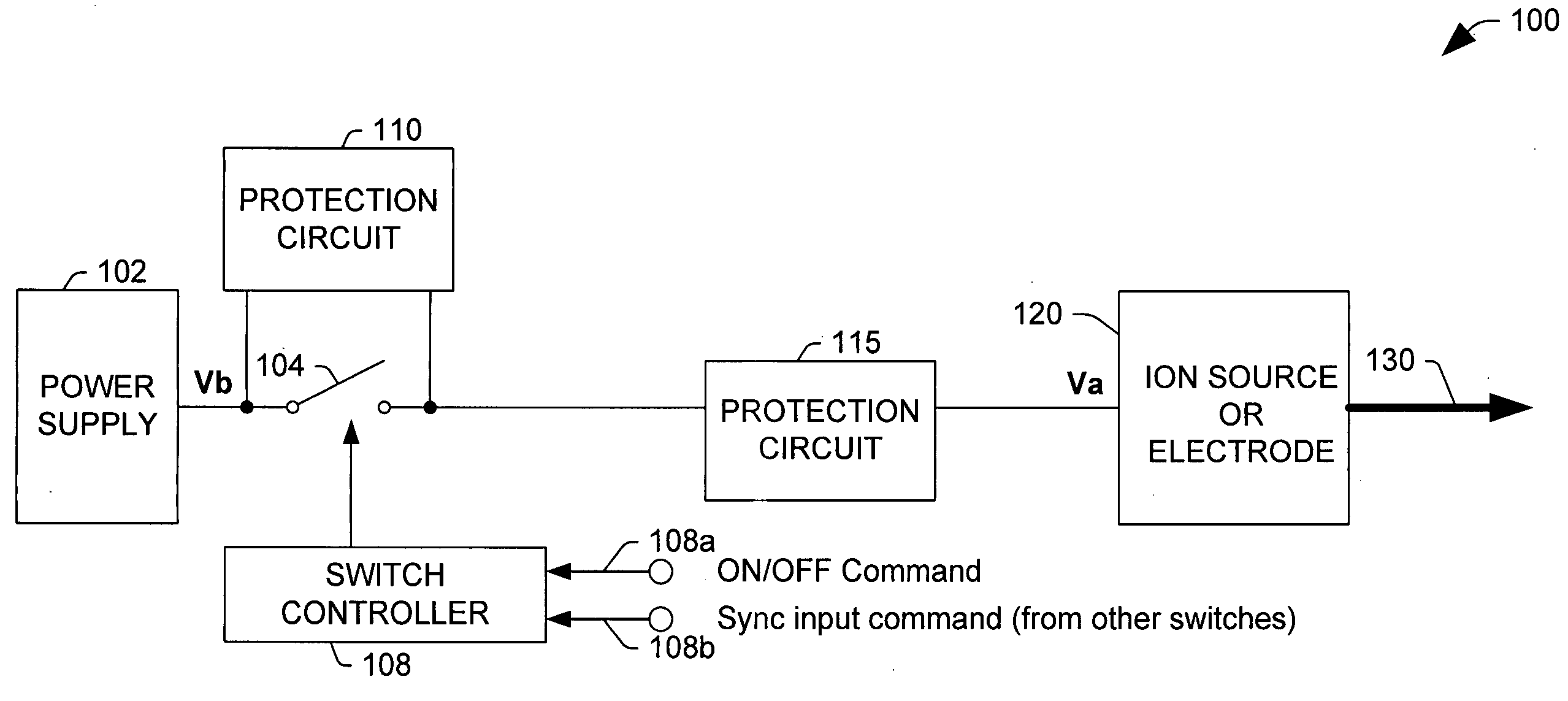
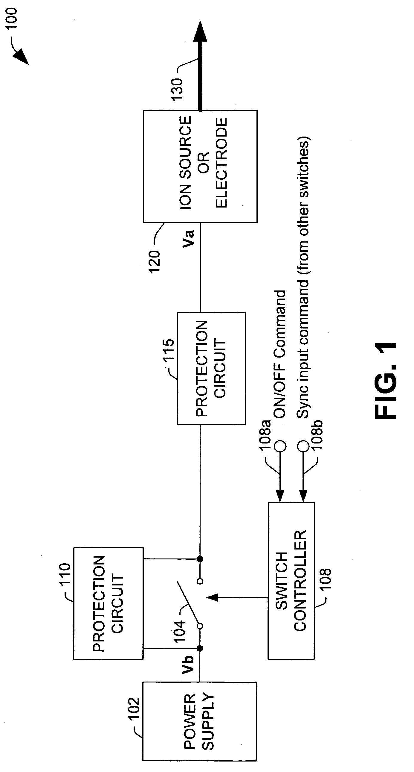
[0043]The present invention relates to ion beam control circuits and methods to minimize particle contamination in an ion implantation system, for example, due to beam strike within the implanter. The present invention seeks to reduce this particle contamination by reducing the beam duty factor or on-time of the beam, by turning off, for example, either the ion extraction or the plasma inside the arc chamber. For example, in order to turn off the ion extraction, one can turn off the extraction voltage and t...


PUM


Abstract

The present invention is directed to a beam control circuit and method used to minimize particle contamination in an ion implantation system by reducing the duty factor of the ion beam. In one embodiment the beam control circuit comprises a,high voltage switch connected in series with a power supply and an ion source portion of the ion implantation system, wherein the switch is operable to interrupt or reestablish a connection between the power supply and an electrode of the ion source including electrodes for plasma production. The beam control circuit also comprises a switch controller operable to control the duty factor of the ion beam by controlling the switch to close before a start of ion implantation and to open after a completion of implantation or at other times when the beam is not needed, thereby minimizing beam duty and particle contamination. The beam control technique may be applied to wafer doping implantation and duty factor reduction. Protection circuits for the high voltage switch absorb energy from reactive components and clamp any overvoltages.

Description

FIELD OF THE INVENTION[0001]The present invention relates generally to ion implantation systems, and more particularly to a beam control circuit used to minimize particle contamination in an ion implantation system, and to a method of reducing the duty factor of the ion beam from an ion source to minimize particle contamination using a high voltage switch between a power supply and an electrode associated with the ion source to initiate or terminate the ion beam during ion implantation operations.BACKGROUND OF THE INVENTION[0002]Ion implantation systems are used to impart impurities, known as dopant elements, into semiconductor substrates or wafers, commonly referred to as workpieces. In such systems, an ion source ionizes a desired dopant element, and the ionized impurity is extracted from the ion source as a beam of ions. The ion beam is directed (e.g., swept) across respective workpieces to implant ionized dopants within the workpieces. The dopant ions alter the composition of th...

Claims


Application Information

Patent Timeline
Patent Type & Authority Applications(United States)
IPC IPC(8): H05B37/00
CPCH01J37/045H01J37/248H01J37/3023H01J2237/08H01J2237/0206H01J2237/0213H01J2237/0432H01J37/3171H01J37/30H01L21/265
Inventor HUANG, YONGZHANGWEIGUO, QUEJINCHENG, ZHANG
Owner AXCELIS TECHNOLOGIES
Why Eureka
Try Eureka