Motor drive with damper

a technology of damper and motor drive, which is applied in the direction of motor/generator/converter stopper, dynamo-electric converter control, instruments, etc., can solve the problems of increased weight and heat retention caused by shields, difficult to keep the common mode voltage under control, and risk of motor damag

Active Publication Date: 2006-06-27
HAMILTON SUNDSTRAND CORP
View PDF6 Cites 24 Cited by
  • Summary
  • Abstract
  • Description
  • Claims
  • Application Information

AI Technical Summary

Benefits of technology

[0009]The present invention is directed to a motor controller having a damper that dampens resonance in a motor drive and prevents a common mode filter from generating a high common mode voltage in response to the motor drive operating at the resonant frequency of the common mode filter. The damper is connected to an output feeder line of a motor drive in the motor controller and provides a common mode path to ground for the common mode filter. Thus, even if the motor drive is operating at a resonant frequency of the common mode filter, the resulting resonance in the common mode filter is attenuated by rather than amplified by the common mode filter.

Problems solved by technology

Although shielding of input and / or output lines of the motor drive is often used to control EMI emissions, there are weight-sensitive applications, such as aircraft applications, the extra weight and heat retention caused by the shields would be unacceptable.
However, for motor drive operating frequencies below the emission requirement limits, it may be difficult to keep the common mode voltage under control because the common mode filter itself has a resonant frequency.
Because the motor drive operates over a wide frequency range, there are opportunities for the motor drive frequency to pass through the common mode filter resonant frequency and excite the common mode filter, thereby creating a risk of motor damage due to the resulting high voltage response.
Harmonics of the voltage output of the motor drive may also create undesirable levels of common mode voltage.

Method used


Image

  • Motor drive with damper
  • Motor drive with damper
  • Motor drive with damper

Examples


Embodiment Construction

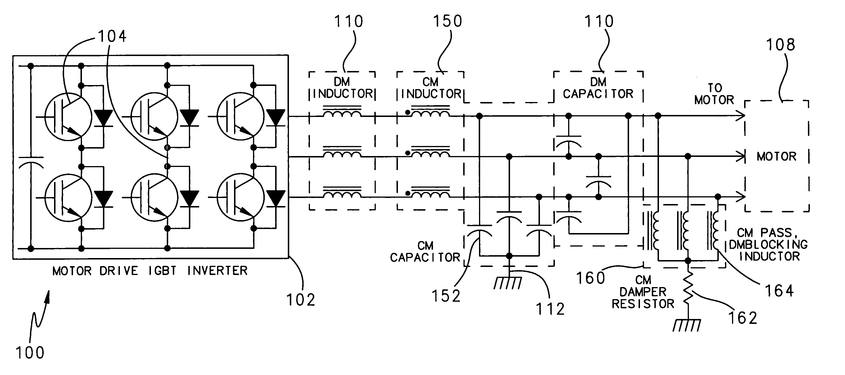
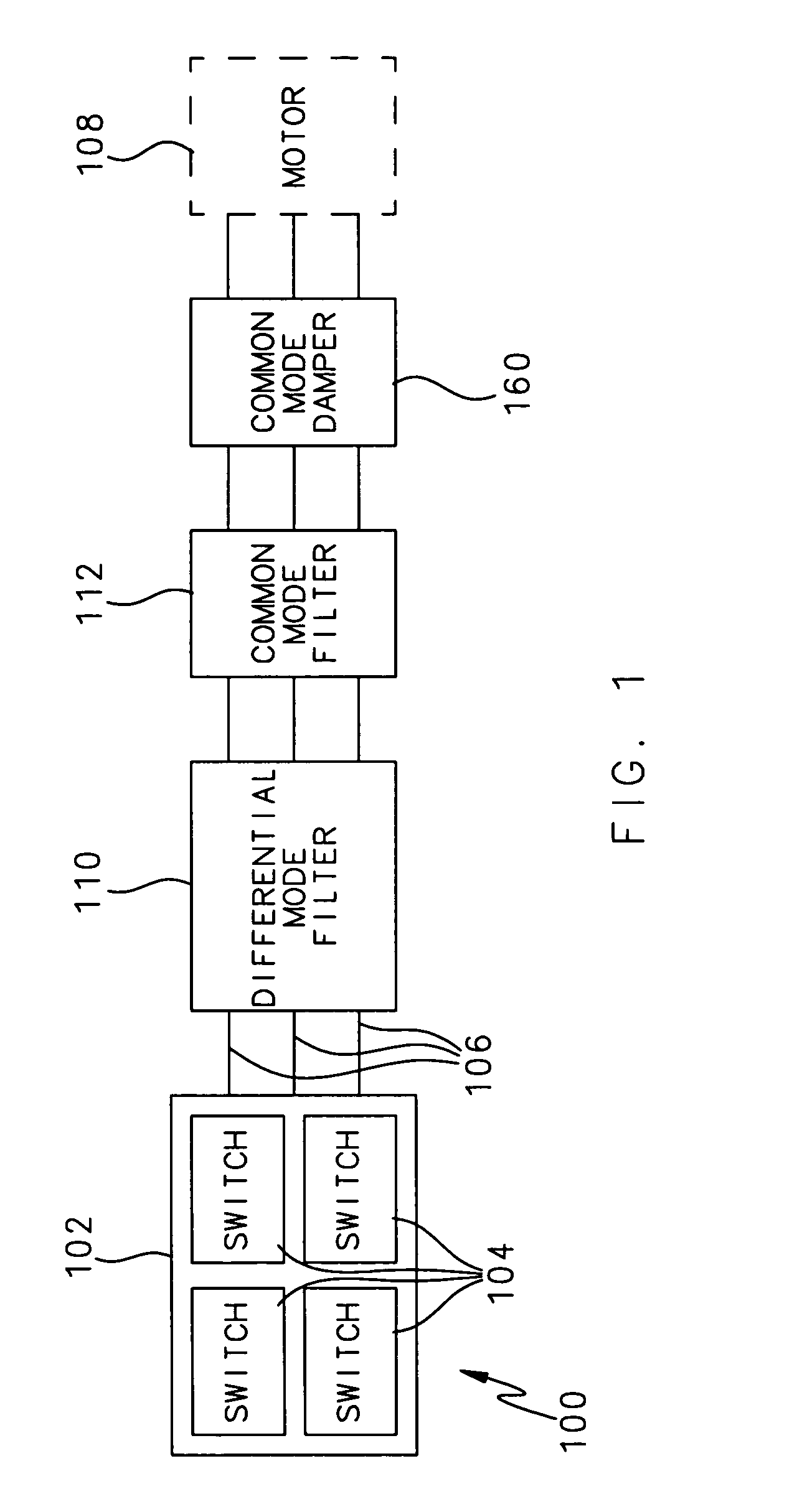
[0012]FIG. 1 is a representative block diagram of an output portion of a motor controller 100 according to one embodiment of the invention. The motor controller 100 includes a motor drive 102 having one or more switches 104 and a plurality of output feeder lines 106 that connect to a motor 108. In the illustrated example, the motor 108 is a three-phase motor and each output feeder line 106 corresponds to one of the phases of the motor 108.

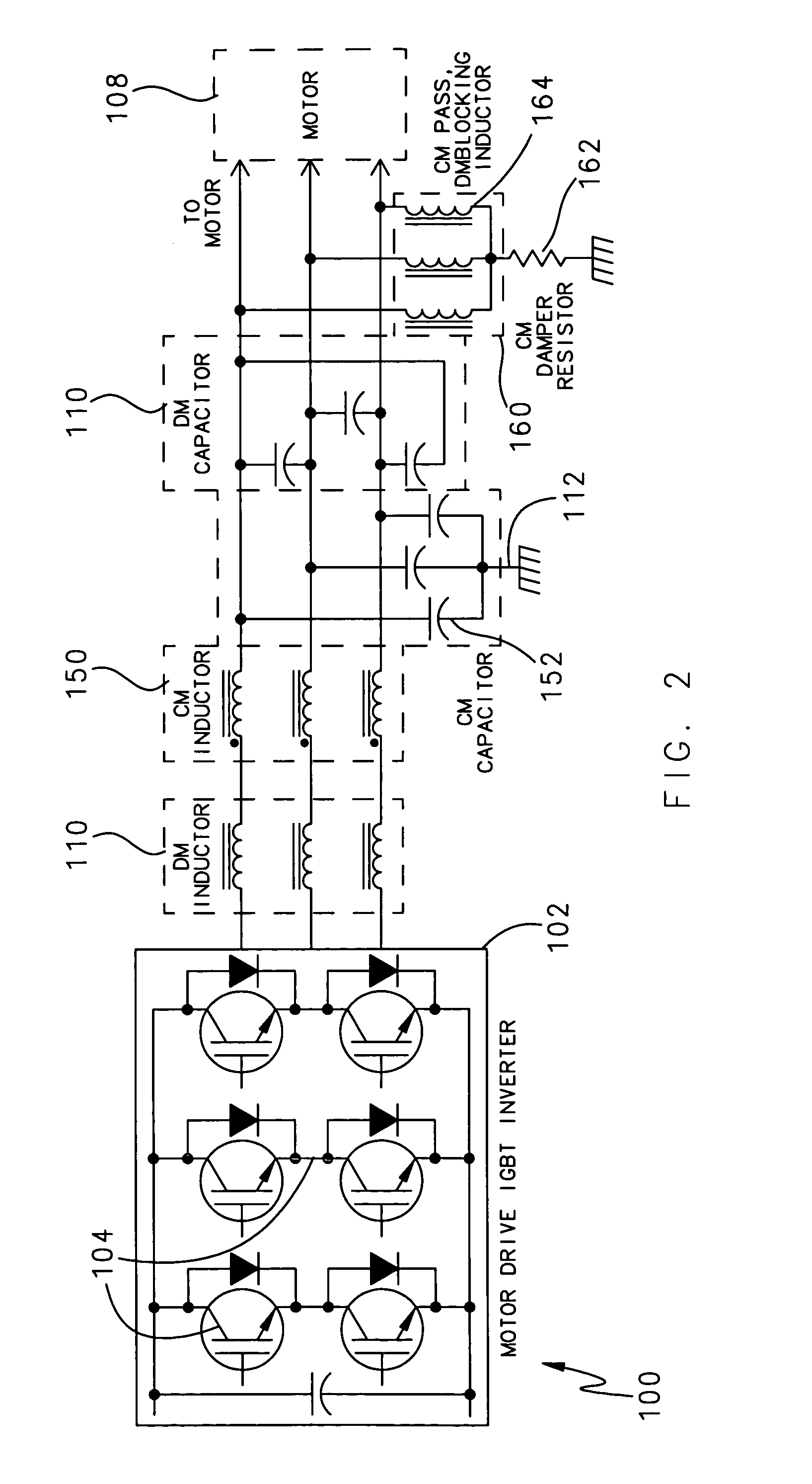
[0013]An optional differential mode filter 110 may be connected to each output feeder line 106 to protect the motor 108 from voltage and current spikes. In the example shown in FIG. 2, the differential mode filters 110 comprise inductors and capacitors, but any other components may be used as the differential mode filters 110. Note that the differential mode filters 110 shown in this example are merely for illustrative purposes only and may be omitted from the motor controller 100 without departing from the scope of the invention.

[0014]A common mod...


PUM


Abstract

A motor controller having a damper that dampens resonance in a motor drive of a common mode filter to prevent it from becoming over excited by operation of the motor drive at a resonant frequency of the common mode filter. The damper is connected to an output feeder line of a motor drive in the motor controller and provides a common mode path to ground for the common mode filter. Thus, even if the motor drive is operating at a resonant frequency of the common mode filter, the resulting resonance in the common mode filter is attenuated by rather than amplified by the common mode filter, thereby preventing the common mode filter from excessive excitation.

Description

TECHNICAL FIELD[0001]The present invention relates to motor controllers, and more particularly to a motor control circuit for filtering a motor drive output.BACKGROUND OF THE INVENTION[0002]Motor controllers are used with motors to provide variable and controllable speed for various applications. The same motor controller may be used for different applications in the same system; for example, a motor controller in an aircraft may be used to start a main engine and to drive an environmental control system.[0003]To minimize the size and weight of the motor used in a given application, it is common to drive the motor at high rotational speeds. This in turn requires the motor controller to operate at relatively high frequencies. To do this, the motor controller may include a motor drive having switches, such as switching transistors, with switching frequencies that can handle the rotational speed of the motor. However, it is also necessary to prevent excessive radiated electromagnetic i...

Claims


Application Information

Patent Timeline
Patent Type & Authority Patents(United States)
IPC IPC(8): G05B5/01
CPCH02M1/126H02P29/0038H03H7/427H03H7/1725H03H7/06H02P29/50H02M1/123
Inventor BAKER, DONAL E.
Owner HAMILTON SUNDSTRAND CORP
Why Eureka
Try Eureka