Switching power supply circuit and overcurrent protection method for the switching power supply circuit

Inactive Publication Date: 2006-06-27
TAIYO YUDEN KK
View PDF4 Cites 29 Cited by
  • Summary
  • Abstract
  • Description
  • Claims
  • Application Information

AI Technical Summary

Benefits of technology

[0047]In accordance with the present invention, a switching power supply circuit that has rapid startup time and excellent response to sudden load fluctuations, and that is capable of reliably protecting against breakdown due to overcurrent in circuit elements and the like with a simple structure can be provided, as can an overcurrent protection method for the switching power supply circuit, by adopting a configuration in which a switching power supply circuit has a switching element for controlling the on/off state of an input power supply according to a drive pulse generated on the basis of a clock pulse having a prescribed period, for allowing electric current to flow from the input power supply to a load by the on-control to the switching element, and allowing flywheel current to f

Problems solved by technology

As a result of these facts, the circuit can break down in a worst case.
H7-46828 and H11-341791 have the problem of reduced responsiveness, because they reduce the switching frequency when overcurrent is detected, and a configuration that uses a timer circuit has problems whereby the timing period of the timer circuit is difficult to set, and the switching cycle of the switching power supply circuit is effectively lengthened, yielding inadequate performance if the

Method used


Image

  • Switching power supply circuit and overcurrent protection method for the switching power supply circuit
  • Switching power supply circuit and overcurrent protection method for the switching power supply circuit
  • Switching power supply circuit and overcurrent protection method for the switching power supply circuit

Examples


Embodiment Construction

[0062]A detailed description of the switching power supply circuit and the overcurrent protection method for the switching power supply circuit according to the present invention will be given with reference to the accompanying drawings.

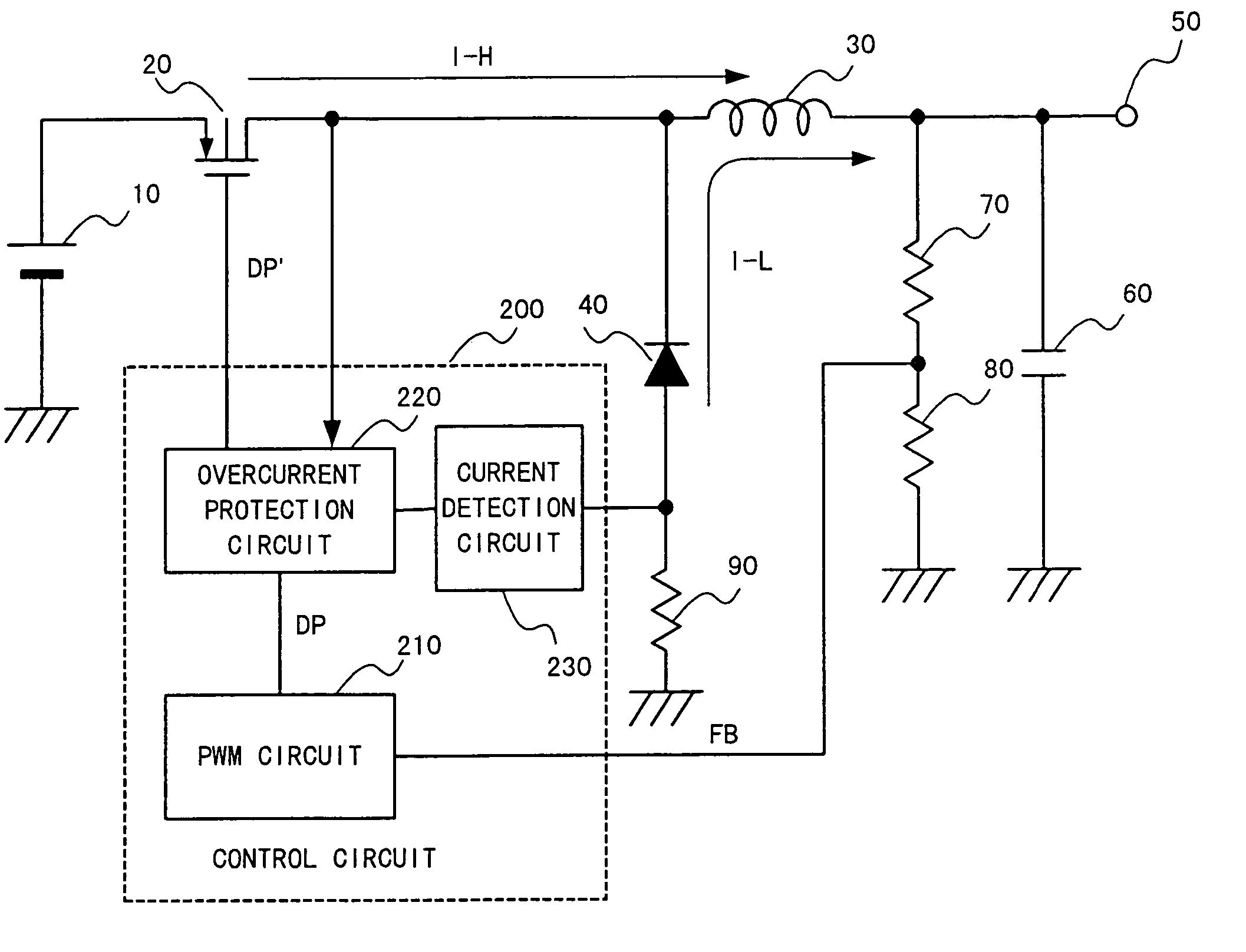
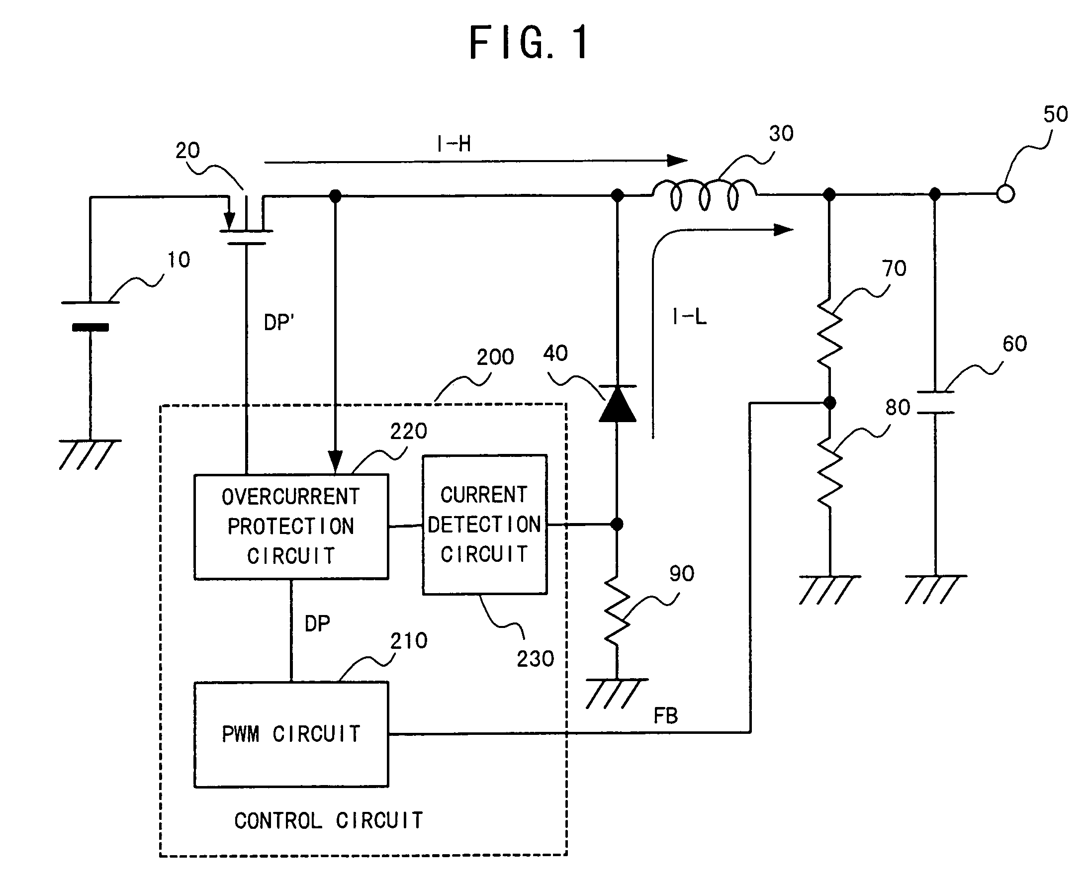
[0063]FIG. 1 is a circuit diagram schematically depicting the structure of a switching power supply circuit according to the switching power supply circuit and overcurrent protection method for the switching power supply circuit according to the present invention

[0064]In FIG. 1, the same symbols are used as are used in FIG. 9 for convenience in describing components that fulfill the same functions as in the conventional circuit depicted in FIG. 9.

[0065]In FIG. 1, the switching power supply circuit constitutes a step-down DC-DC converter the same as the conventional switching power supply circuit depicted in FIG. 9. In this switching power supply circuit, a transistor (field-effect transistor) 20 acts as a switching element, and an input power supply ...


PUM


Abstract

A switching power supply circuit comprises a switching element for controlling the on/off state of an input power supply according to a drive pulse generated on the basis of a clock pulse having a prescribed period. Breakdown of circuit elements due to current superposition is effectively prevented by detecting current flowing through the switching element and flywheel current, and comparing these detected results with a first and second reference value, respectively. An overcurrent detection circuit detects that the current flowing through a transistor for controlling the on/off state of the input power source has reached a first reference value, a flywheel current detection circuit detects flywheel current, an overcurrent protection operation is performed for turning off the transistor based on the detected output of the overcurrent detection circuit, and the transistor is turned on during the overcurrent protection operation at the timing of the clock pulse after the flywheel current detected by the flywheel current detection circuit has reached the second reference value.

Description

BACKGROUND OF THE INVENTION[0001]1. Field of the Invention[0002]The present invention relates to a switching power supply circuit and an overcurrent protection method for the switching power supply circuit, and particularly relates to a switching power supply circuit and an overcurrent protection method for the switching power supply circuit whereby reliable protection is provided against breakdown of circuit elements and the like due to overcurrent.[0003]2. Description of the Related Art[0004]FIG. 9 is a circuit diagram depicting an example of a conventional switching power supply circuit. The switching circuit depicted in FIG. 9 constitutes a step-down DC-DC converter. In this switching circuit, a field-effect transistor (hereinafter referred to simply as “transistor”) 20 is used as a switching element. A direct current outputted from an input power supply 10 is stepped down by controlling the on / off state of the transistor 20 by means of a drive pulse DP′ from a control circuit 1...

Claims


Application Information

Patent Timeline
IPC IPC(8): G05F1/40H02M7/21G05F1/575H02M3/155H02M3/156
CPCG05F1/575H02M3/156H02M1/32
Inventor OKADA, TERUO
Owner TAIYO YUDEN KK
Why Eureka
Try Eureka