Three-dimensional imaging device

a three-dimensional imaging and imaging device technology, applied in the direction of mirrors, instruments, mountings, etc., can solve the problems of limiting the depth resolution and the possible range of depth of the three-dimensional image, slow response time and complex driving mechanisms to control the relative position of the refractive lens, and slow response time typically on the order of hundreds of milliseconds

Active Publication Date: 2006-06-27
STEREO DISPLAY
View PDF8 Cites 67 Cited by
  • Summary
  • Abstract
  • Description
  • Claims
  • Application Information

AI Technical Summary

Benefits of technology

[0005]An objective of the invention is to provide a real-time three-dimensional imaging system that can get an all-in-focus image and depth information of the image.
[0006]Another objective of the invention is to provide a three-dimensional imaging system that can compensate various optical distortions or aberrations.

Problems solved by technology

Besides, the lens has a small focal plane variation in the range of −4 mm to 4 mm, which limits the possible range of depth and the depth resolution of the three-dimensional image.
It has a slow response time and complex driving mechanisms to control the relative position of the refractive lenses.
Unfortunately, it has a slow response time typically on the order of hundreds of milliseconds.
Even though the fastest response liquid crystal lens has a response time of tens of milliseconds, it has a small focal length variation and a low focusing efficiency.
A new three-dimensional imaging device is needed to overcome the problems of the prior arts that used variable focal length lenses that are slow, have small focal length variation and low focusing efficiency, and / or have a complex control mechanism.

Method used


Image

  • Three-dimensional imaging device
  • Three-dimensional imaging device
  • Three-dimensional imaging device

Examples


Embodiment Construction

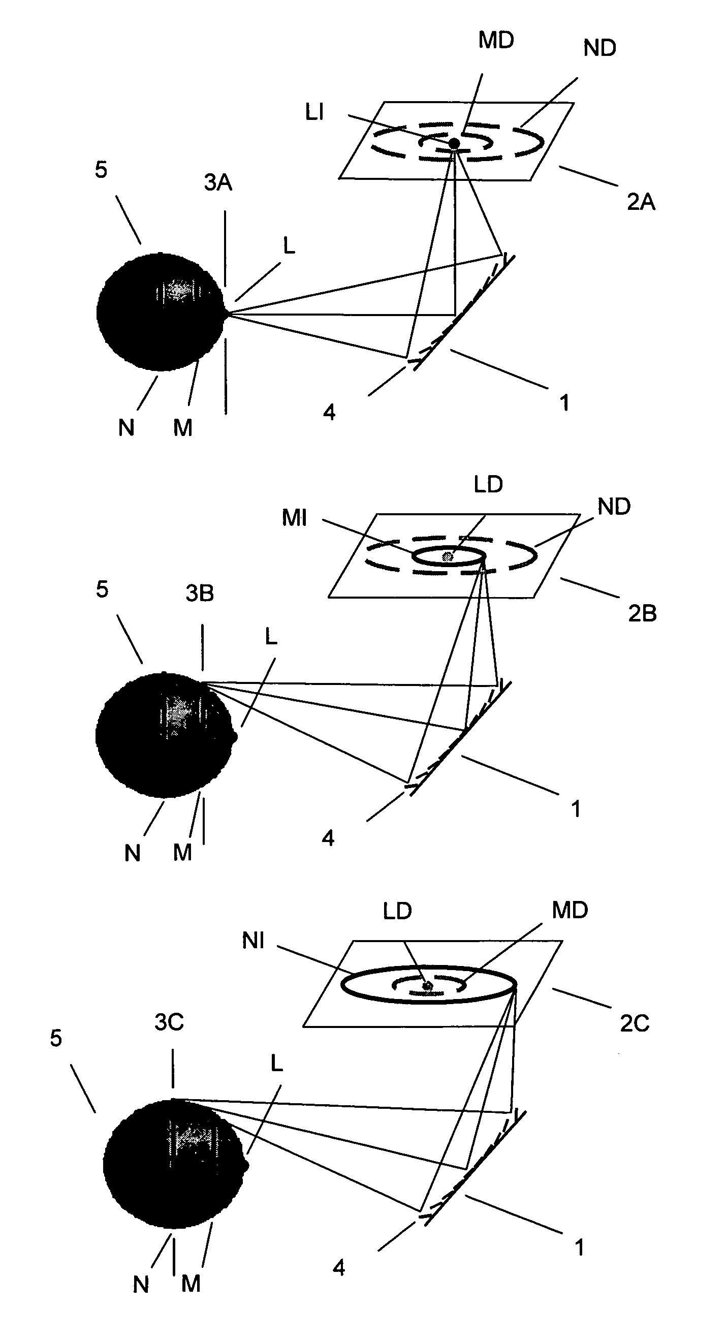
[0039]FIG. 1 shows how a micromirror array lens 1 gets original two-dimensional images 2A, 2B, 2C with different focal planes 3A, 3B, 3C. The micromirror array lens 1 includes many micromirrors 4. The focal length of the micromirror array lens 1 is changed by electrostatically and / or electromagnetically controlling each of the micromirrors 4. A focal length change of the micromirror array lens 1 changes the focal plane of the imaging system. Two-dimensional original images 2A, 2B, 2C are taken with the depth information which is obtained from the position of the focal plane. The original two-dimensional image 2A with the first focal plane 3A has in-focus image LI which is the image of the portion L of an object 5. Images MD, ND of portion M, N of an object 5 are defocused. Therefore, the image processing unit determines the in-focus pixels LI from the original two-dimensional images 2A. The focal plane 3A of the first original two-dimensional image 2A gives the depth information of ...


PUM


Abstract

A new three-dimensional imaging device has been needed to overcome the problems of the prior arts that the used variable focal length lenses that are still slow, have small focal length variation and low focusing efficiency, and requires a complex mechanism to control it. The invented three-dimensional imaging system uses the variable focal length micromirror array lens. Since the micromirror array lens has lots of advantages such as very fast response time, large focal length variation, high optical focusing efficiency, large size aperture, low cost, simple mechanism, and so on, the three-dimensional imaging device can get a real-time three-dimensional image with large depth range and high depth resolution.

Description

BACKGROUND OF THE INVENTION[0001]The present invention relates to a three-dimensional imaging device using a micromirror array lens.[0002]Several three-dimensional imaging devices have been proposed and developed. One of them uses a “depth from focus” criterion and fast response variable focal length lens. It is described in T. Kaneko et al., 2000, “Quick Response Dynamic Focusing Lens using Multi-Layered Piezoelectric Bimorph Actuator,”Proceeding of SPIE Vol. 4075: 24–31. This imaging system uses a variable focal length lens comprised of two thin glass diaphragms with a transparent working fluid and multi-layered piezoelectric bimorph actuator mounted thereon. To get a three-dimensional image, the criterion of “depth from focus” achieves an all-in-focus image and three-dimensional reconstruction, simultaneously. Since the variable focal length lens has a slow focal length change speed of 150 Hz, the system can have only 5 focal plane shifts when about 30 Hz is considered for the af...

Claims


Application Information

Patent Timeline
Patent Type & Authority Patents(United States)
IPC IPC(8): G02B26/00G02B26/08G02B7/182G02B27/10G02B27/22H04N13/00
CPCH04N13/0235G02B27/2285G02B27/2235G02B26/0833G02B30/35G02B30/54H04N13/236
Inventor GIM, DONG WOOSEO, CHEONG SOOCHO, GYOUNG ILKIM, TAE HYEON
Owner STEREO DISPLAY
Why Eureka
Try Eureka