Signal distribution within customer premises

Inactive Publication Date: 2006-06-27
QWEST
View PDF6 Cites 53 Cited by
  • Summary
  • Abstract
  • Description
  • Claims
  • Application Information

AI Technical Summary

Problems solved by technology

A principle factor in the cost of adding a service such as VDSL is the installment of new wiring to the gateway and from the gateway to receivers.

Method used


Image

  • Signal distribution within customer premises
  • Signal distribution within customer premises
  • Signal distribution within customer premises

Examples


Embodiment Construction

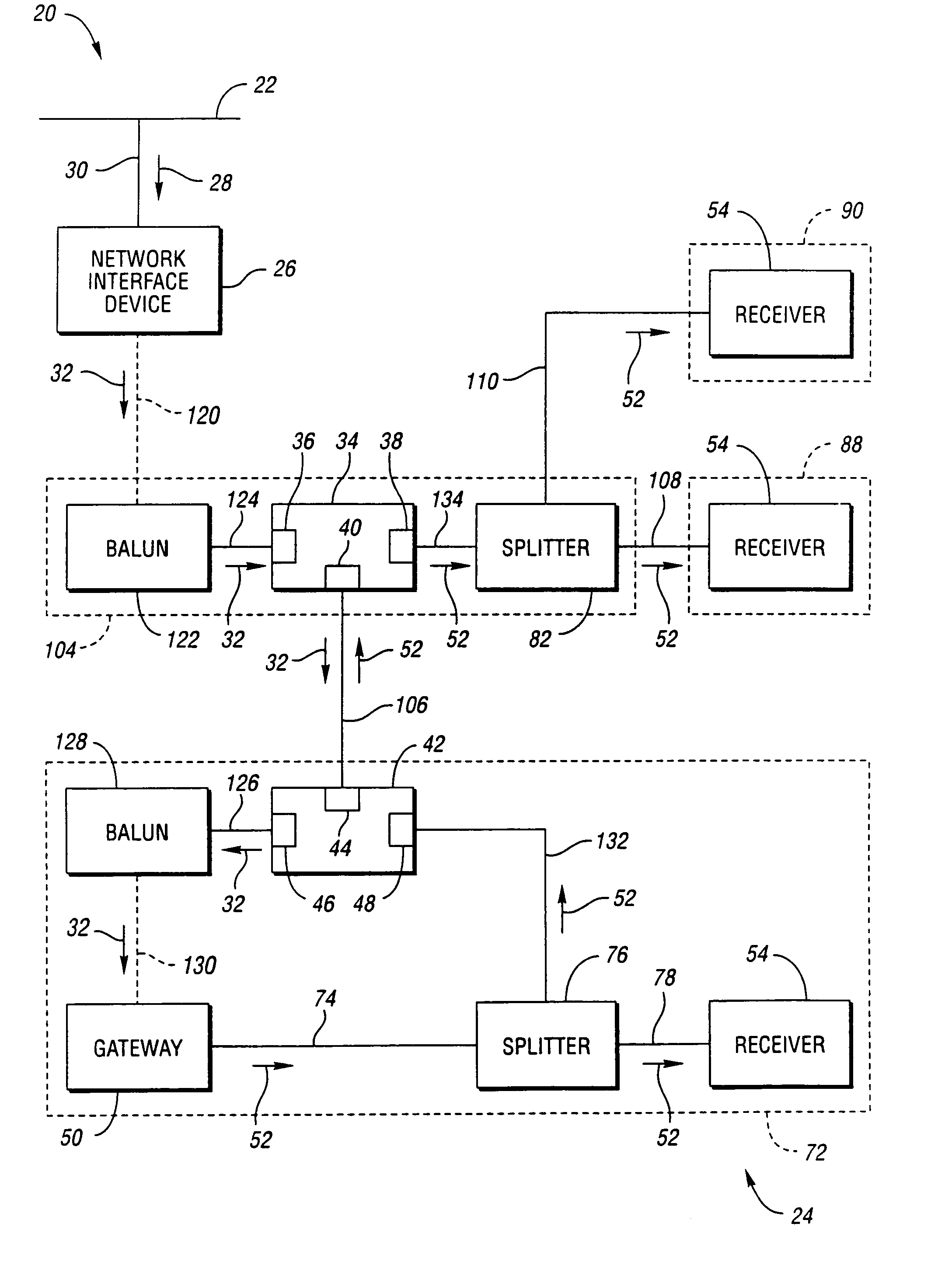
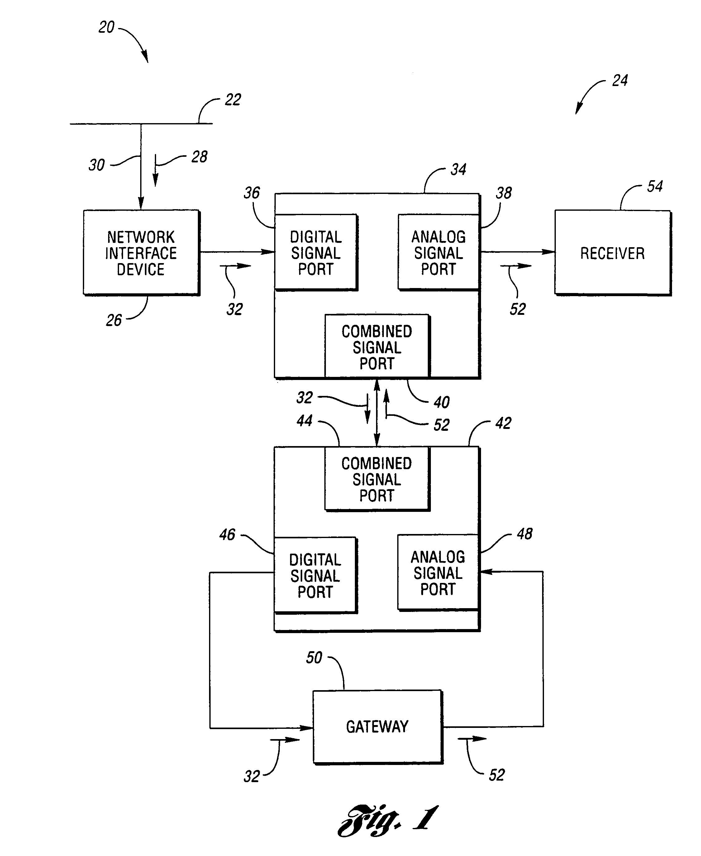
[0023]Referring to FIG. 1, a schematic drawing of a system for distributing data signals from a telecommunication network according to an embodiment of the present invention is shown. A data signal distribution system, shown generally by 20, includes telecommunication network 22 providing information to a plurality of customer premises, one of which is indicated by 24. Customer premises 24 includes network interface device 26 receiving digital signals 28 from telecommunication network 22 through network connection point 30. Network interface device 26 may provide several services. First, network interface device 26 electrically isolates customer premises 24 from the remainder of distribution system 20, reducing the possibility that voltage transients on telecommunication network 22 will damage customer premises equipment. Network interface device 26 may also serve as a bridge to permit standard telephone signals (POTS) to pass between telecommunication network 22 and POTS equipment ...


PUM


Abstract

Data signals from a telecommunication network are routed to a gateway which generates analog signal distributed to receivers within a customer premises. A network interface device receives digital signals from the telecommunication network. A first diplexer has a digital signal port connected to the network interface device. The first diplexer combined signal port is connected with the combined signal port of a second diplexer. The gateway receives digital signals from the second diplexer digital signal port and provides analog signals to the second diplexer analog signal port. Analog signals are then available to receivers at both the first diplexer analog signal port and the second diplexer analog signal port.

Description

CROSS-REFERENCE TO RELATED APPLICATIONS[0001]This application is a continuation of U.S. application Ser. No. 09 / 514,727 filed Feb. 28, 2000 now abandoned.TECHNICAL FIELD[0002]The present invention relates to routing analog and digital information within customer premises.BACKGROUND ART[0003]Customers have an increasing selection of sources for information, entertainment, and communication services. These sources offer a variety of data formats carried over many types of media, including twisted pair, coaxial cable, fiber, radio waves, and the like. Customer premises that were once wired for at most two formats, standard telephone and cable TV, are now often rewired to accommodate new data formats and media.[0004]An example is a customer wired for traditional point-to-multipoint broadband reception, commonly known as cable TV. Such a customer typically has coaxial cable running from a network connection point to locations where analog receivers may be located. When high speed digital...

Claims


Application Information

Patent Timeline
Patent Type & Authority Patents(United States)
IPC IPC(8): H04J1/00H04N7/10
CPCH04N7/108H04N7/106
Inventor CAMPBELL, KURT A.PHILLIPS, BRUCE A.
Owner QWEST
Why Eureka
Try Eureka