Supercharge Your Innovation With Domain-Expert AI Agents!

True DTMF dialer

a dialer and dialing technology, applied in the field of true dtmf dialing, can solve the problems of high software development and handling costs, the potential of quickly turning into an implementation nightmare for software engineers, and the complexity of conventional digital telephone systems

Inactive Publication Date: 2006-06-27
AVAGO TECH WIRELESS IP SINGAPORE PTE +1
View PDF2 Cites 3 Cited by
  • Summary
  • Abstract
  • Description
  • Claims
  • Application Information

AI Technical Summary

Benefits of technology

[0030]A method of digitally generating tones in accordance with another aspect of the present invention comprises inputting a plurality of tone commands into a dial buffer accessible by a first processor. A sequence of tone command information is output from the dial buffer to a tone generator. The output sequence of tone command information is sequentially presented to a tone generator. Tones are generated on a fixed timing basis when more than one non-null tone command is available in the dial buffer, and tones are generated on a continuous basis when only one non-null tone command is available in the dial buffer.

Problems solved by technology

Although the integration of DTMF generation within a DSP has reduced hardware costs, it has caused a substantial amount of cost in the development and handling of software necessary to guarantee that stringent regulatory timing requirements for the transmission of DTMF tones be adhered to.
However, due to the stringent timing requirements of DTMF dialing, what might start as an inexpensive solution has the potential of quickly turning into an implementation nightmare for software engineers.
Accordingly, conventional digital telephone systems have a timing complexity which is exacerbated by at least two factors.
First, the controller may be busy processing other tasks while simultaneously determining the timing of generation of the DTMF signal instructions.
Secondly, the DSP may be busy and therefore not be able to send an acknowledgment at the time that the controller determines that the next DTMF signal instruction should be sent, therefore requiring the instruction to be resent.
Thus, using current technology, the use of a DSP for DTMF generation is complicated by the fact that either or both a DSP and a controller may be busy with other tasks at the time that the next DTMF tone transmission or tone stoppage should take place.
It would prove to be a fairly expensive item if all the DSP performed was DTMF tone generation.
Unfortunately, since the DSP is also used for functions other than generating DTMF, the DSP may be busy at the specific time that the controller desires a DTMF tone to be output.
Unfortunately, control of DTMF tone output by one processor for output by another processor inherently includes timing ‘jitter’ or differences between the length of each DTMF tone and the pauses therebetween, particularly as the workload and interrupt servicing of the DSP increases.
Accordingly, while the microcontroller tries to maintain accurate and consistent digit / pause periods by sending timely start / stop DTMF generator commands to the DSP, often the resulting DTMF digits output to the telephone line do not comply with the regulatory requirements for accuracy and consistency.
The problem is worse still in PC telephony applications where the controlling software is unable to keep accurate timing due to the multi-tasking nature of PC processors.
Unfortunately, a problem with this solution is that it does not allow for the possibility of manual dialing on a keypad where digits are dialed on the fly, at varying lengths.

Method used


Image

  • True DTMF dialer
  • True DTMF dialer
  • True DTMF dialer

Examples


Embodiment Construction

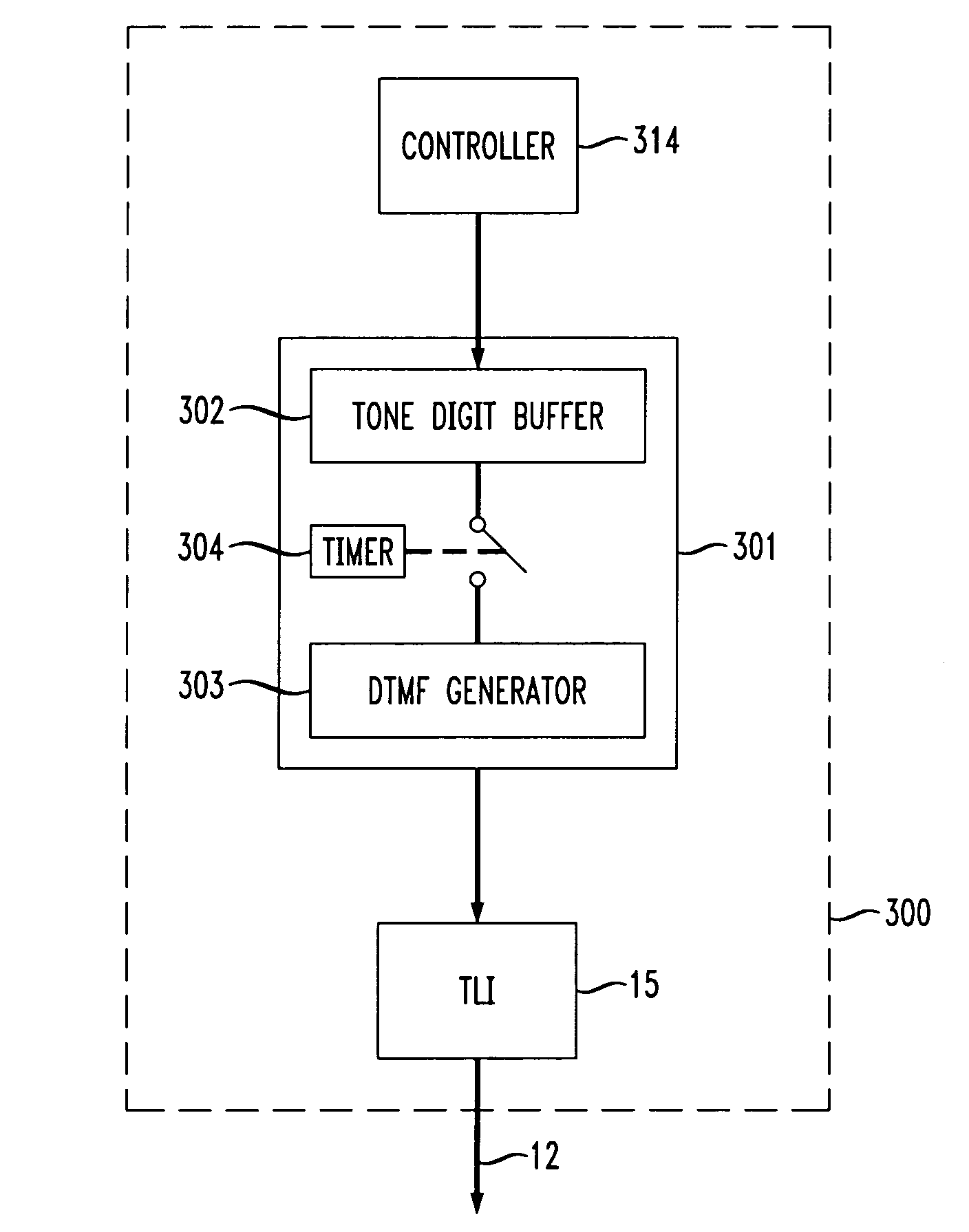
[0036]The present invention implements a circular dial buffer in appropriate random access memory (RAM) accessible by the DSP (e.g., 16 or 32 bytes minimum) for the purpose of storing and dialing out DTMF digits. Although the DSP can use default digit / pause timings consistent with speed dial techniques, the processor (e.g., microcontroller) is able to customize such parameters to suit the needs of the particular application.

[0037]To the processor, the DSP appears to behave much like an off-the-shelf stand alone touch tone dialer, with the exception that the DSP does not have access to a keypad input. Instead, the manual timing associated with keypad input is simulated by the processor in commands to the DSP. Thus, instead of inputting rows and columns or other information relating to button activation on a keypad to input touch tone digits, the principles of the present invention utilize DSP commands sent from the processor to the DSP to mimic manual activation of keys being pressed...


PUM


Abstract

A circular dial buffer is implemented in appropriate random access memory (RAM) accessible by a DSP for the purpose of storing DTMF digits to be generated and output on, e.g., a telephone line. To the processor, the DSP appears to behave much like an off-the-shelf stand alone touch tone dialer, with the exception that the DSP does not have access to a keypad input. Instead, in addition to speed dial capabilities, mimicked keypad input is transmitted by a controller to the DSP rather than timing information. Thus, instead of requiring the input of rows and columns or other information relating to button activation on a connected keypad to input touch tone digits, the principles of the present invention allow mimicking of keypad input using commands sent by the controller to the DSP, e.g., a first command indicating that a mimicked, manually operated key is being pressed, and a second command indicating that the mimicked key has been released. Thus, the processor in a processor / DSP telephony system is no longer required to send precisely timed start / stop commands at precise intervals for directing the timing of a DTMF generator implemented in the DSP. Instead, touch tone digit commands may be sent by the processor to the circular dial buffer in the DSP as fast as the processor-to-DSP interface will permit. Accordingly, the present invention provides for the generation of DTMF tone signals from a DSP either based on pre-programmed timing parameters for automatic dialing, but also in accordance with mimicked keypad activity transmitted from the controller to the DSP to affect a true DTMF dialer in the DSP.

Description

BACKGROUND OF THE INVENTION[0001]1. Field of the Invention[0002]This invention relates generally to dual tone multiple frequency (DTMF) generation. More particularly, it relates to a method and apparatus allowing a processor (e.g., a digital signal processor) to behave as though it is a true dialer capable of seamlessly intermixing keypad input and automatic dialing, without the need for direct access to a keypad.[0003]2. Background of Related Art[0004]Digital telephone devices such as digital telephones and digital telephone answering devices have become commonplace. Such devices typically include a processor (e.g., a controller or microprocessor) for handling overall control of the telephone device, and another processor such as a DSP to handle time intensive tasks such as DTMF tone generation and / or detection.[0005]DTMF tones (i.e., touch tones) are typically used to communicate information, e.g., a telephone number, over a telephone line. At first, external DTMF generator circui...

Claims


Application Information

Patent Timeline
Patent Type & Authority Patents(United States)
IPC IPC(8): H04M1/00
CPCH04M1/505
Inventor BELHAJ, SAID O.
Owner AVAGO TECH WIRELESS IP SINGAPORE PTE
Features
  • R&D
  • Intellectual Property
  • Life Sciences
  • Materials
  • Tech Scout
  • Unparalleled Data Quality
  • Higher Quality Content
  • 60% Fewer Hallucinations
Learn More