Antenna transmission and reception system

a technology of transmission and reception system, applied in the direction of polarisation/directional diversity, electromagnetic wave modulation, wireless commuication services, etc., can solve the problems of inability to increase transmission efficiency, difficult beam formation, and insufficient transmission power to mobile stations through these paths. , to achieve the effect of increasing transmission efficiency

Active Publication Date: 2006-06-27
NEC CORP
View PDF9 Cites 104 Cited by
  • Summary
  • Abstract
  • Description
  • Claims
  • Application Information

AI Technical Summary

Benefits of technology

[0024]It is therefore an object of the present invention to provide an antenna transmission and reception system which is capa...

Problems solved by technology

Accordingly, it is substantially impossible to transmit enough power to mobile stations through these paths.
As described above, in the cell propagation environment having a large difference between t...

Method used


Image

  • Antenna transmission and reception system
  • Antenna transmission and reception system
  • Antenna transmission and reception system

Examples


first embodiment

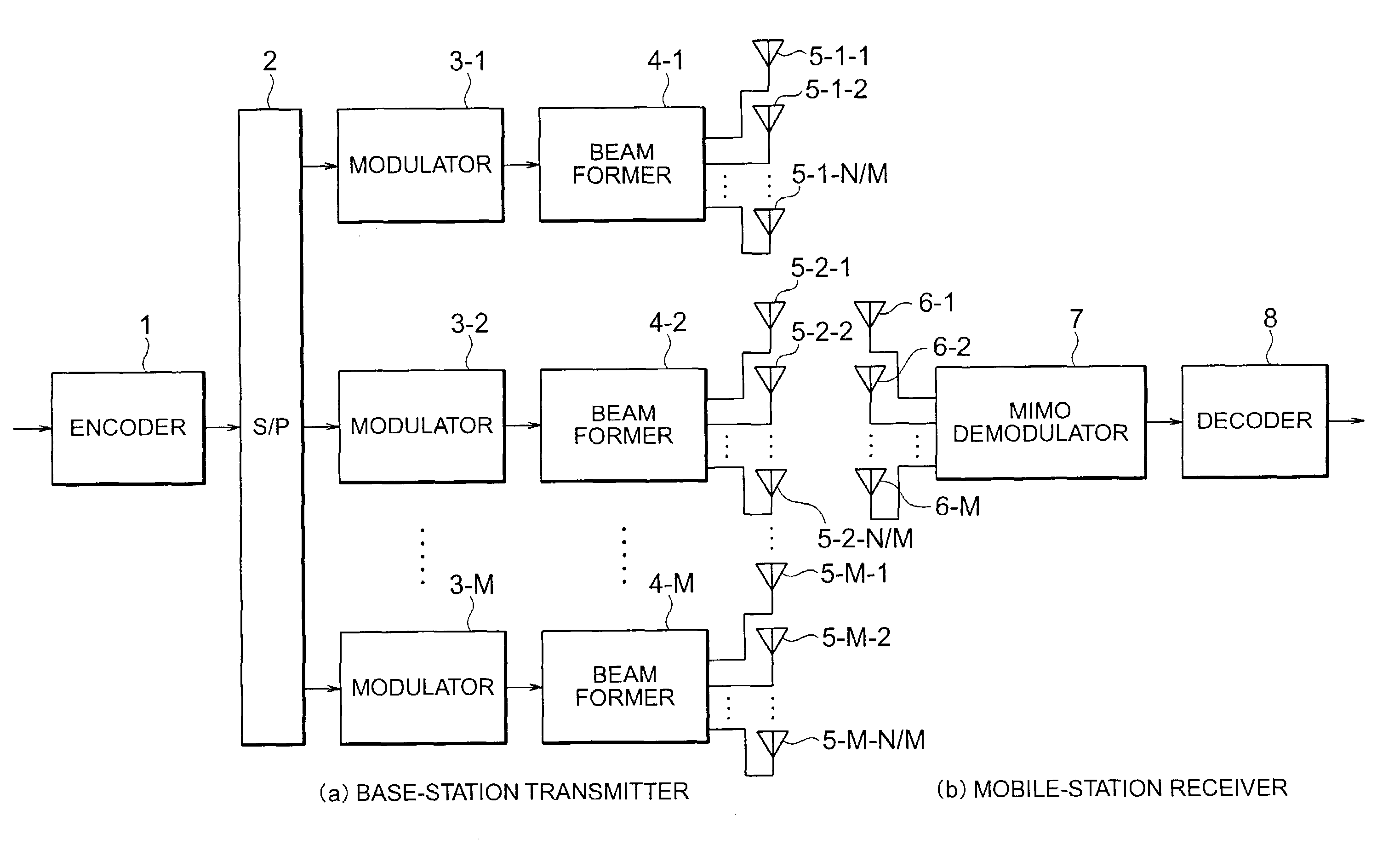
[0054]Referring to FIG. 8, description will be made of the arrangement of an antenna transmission and reception system according to the present invention.

[0055]In the antenna transmission and reception system according to the present embodiment, each base station has a transmitter including N antennas (N is an integer of 2 or more) while each mobile station has a receiver including M antennas (M is an integer of 2 or more). The number of antennas N of the base station can be set to be larger than the number of antennas M of the mobile station. Generally, N is set to 6 to 8 and M is set to 2 to 4.

[0056]In each base station, the antennas are divided into a plurality of array antenna groups in accordance with the transmission environment of a cell. Each array antenna group performs loose directional-beam control. The respective array antenna groups transmit data in parallel (MIMO (Multiple Input Multiple Output) transmission). Reception according to MIMO is performed on the reception s...

second embodiment

[0073]Referring to FIG. 13, the structure of a receiver according to the present invention will be described below.

[0074]In addition, a cell system to which the second embodiment of the present invention is applied will be described with reference to FIG. 14

[0075]According to the present embodiment, as shown in FIG. 14, each small-to-medium-sized cell system 31 has a low-antenna base station 33. In the cell system 31, a plurality of transmission antennas of the base station 33 are divided into a plurality of array antenna groups. Each array antenna group performs loose directional-beam control. The respective array antenna groups transmit different data in parallel. Accordingly, both directional-beam transmission and MIMO transmission are performed. When a mobile station 35 is located in the small-to-medium-sized cell system 31, the mobile station 35 performs MIMO demodulation.

[0076]A large cell system 32 has a high-antenna base station 34. In the large cell system 32, since a usual...


PUM


Abstract

A transmitter of a base station includes a data serial-to-parallel converter, M modulators, M beam formers, and transmission antennas. The data serial-to-parallel converter converts transmission data into M sequences. Each modulator modulates the transmission data. Each beam former weights the modulation signal to form directional beams. The transmission antennas narrow the beams and transmit the modulation signals in parallel (MIMO transmission). In a mobile station, a receiver has reception antennas for receiving data transmitted in parallel and an MIMO demodulator for demodulating the data.

Description

[0001]This application claims priority to prior application JP 2002-146814, the disclosure of which is incorporated herein by reference.BACKGROUND OF THE INVENTION[0002]The present invention relates to an antenna transmission and reception system in a mobile communication system, and in particular, relates to an antenna transmission and reception system in which a large amount of data can be transmitted with high efficiency in each cell.[0003]In future mobile communication cellular systems, an increased traffic of high-rate packet data is expected, particularly, in down links. Accordingly, these systems require the immediate development of wireless transmission methods capable of transmitting a large amount of data with high efficiency. For this development, the following method is currently being studied. This method gives high priority to users in good transmission environments using multilevel modulation methods to realize high-speed data transmission. In addition, array antenna ...

Claims


Application Information

Patent Timeline
IPC IPC(8): H04B1/38H04M1/00H01Q1/24H04B7/06H01Q3/24H01Q3/26H01Q21/08H04B7/04H04B7/08H04B7/26H04W16/24H04W16/28H04W16/30H04W88/02
CPCH01Q1/246H01Q3/24H04B7/0697H01Q21/08H01Q3/26H04B7/0452
Inventor YOSHIDA, SHOUSEI
Owner NEC CORP
Why Eureka
Try Eureka