Apparatus and method for correcting signal imbalances using complex multiplication

Active Publication Date: 2006-06-27
ARRIS ENTERPRISES LLC
View PDF28 Cites 23 Cited by
  • Summary
  • Abstract
  • Description
  • Claims
  • Application Information

AI Technical Summary

Problems solved by technology

One limitation of the system illustrated in FIG. 1 is that it is only capable of processing data from a single transponder at any given time.
In order to concurrently process data from a group of n transponders, all of the logic illustrated in FIG. 1 must be multiplied by n, resulting in significant addit

Method used


Image

  • Apparatus and method for correcting signal imbalances using complex multiplication
  • Apparatus and method for correcting signal imbalances using complex multiplication
  • Apparatus and method for correcting signal imbalances using complex multiplication

Examples


Embodiment Construction

[0040]In the following description, for the purposes of explanation, numerous specific details are set forth in order to provide a thorough understanding of the present invention. It will be apparent, however, to one skilled in the art that the invention may be practiced without some of these specific details. In other instances, well-known structures and devices are shown in block diagram form to avoid obscuring the underlying principles of the invention.

Embodiments of a System and Method for Demodulating and Decoding Multiple Data System

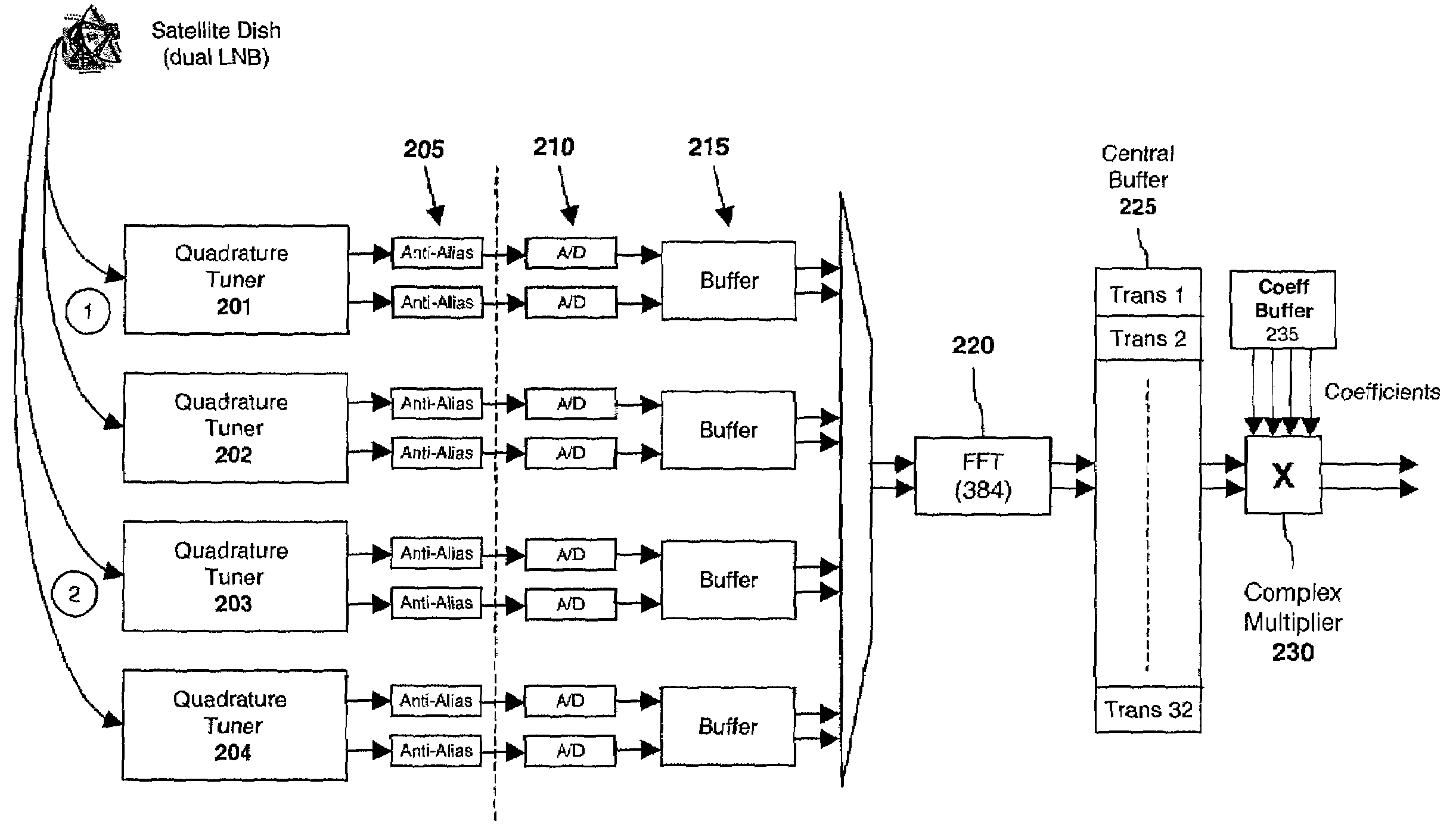
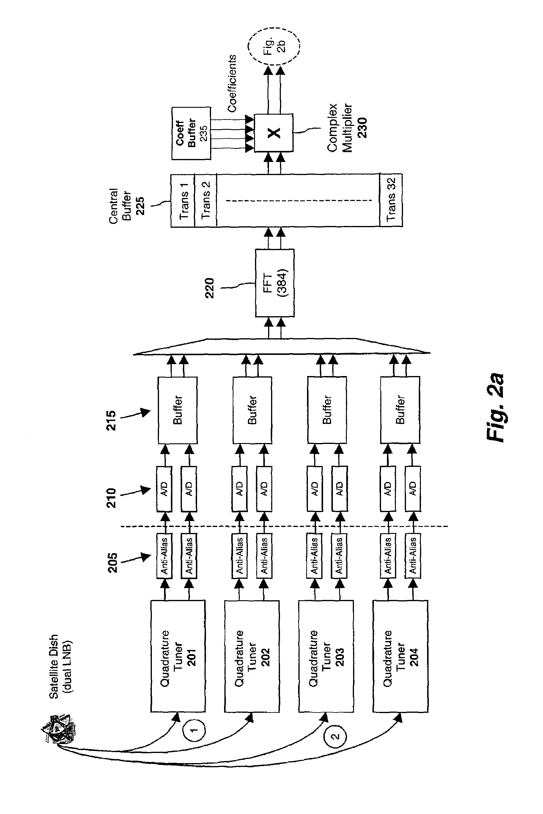
[0041]As illustrated in FIG. 2, one embodiment of the invention is comprised of a plurality of quadrature tuners 201–204, each of which lock on to signals transmitted by a plurality of transponders, downconvert the signals to baseband, and separate the in-phase (“I”) and quadrature phase (“Q”) components of the signals. In one embodiment, the entire group of transponders employed on the satellite system are allocated across the tuners 201–204. Acco...


PUM


Abstract

A complex multiplier is described for filtering a signal in the frequency domain. In one embodiment, additional, independent frequency coefficients are supplied by the complex multiplier so that gain and/or phase of the signal may be independently modified (i.e., gain may be modified without affecting phase and vice-versa).

Description

BACKGROUND[0001]1. Field of the Invention[0002]This invention relates generally to the field of multimedia systems. More particularly, the invention relates to a multimedia system capable of concurrently demodulating and decoding a plurality of multimedia streams transmitted from a satellite or a cable network.[0003]2. Description of the Related Art[0004]Digital broadband video systems, such as digital cable or satellite, multiplex many television channels onto a single carrier. In the cable world, the carriers are modulated using Quadrature Amplitude Modulation (“QAM”). In the satellite world, the carriers (known as transponders) are modulated using Quadrature Phase Shift Key (“QPSK”) modulation. In residential satellite / cable systems, these carriers typically have a net bandwidth of 20–40 Mbits / s.[0005]As illustrated in FIG. 1, a conventional digital receiver 100 is comprised of a tuner 110 for locking on to a signal from a single transponder at a specified frequency and downconve...

Claims


Application Information

Patent Timeline
IPC IPC(8): G06F17/10G06F7/52H04L1/00H04L27/38
CPCH04L1/0054H04L1/0057H04L1/0059H04L27/3872H04L1/0069H04L27/3863H04L1/0065
Inventor PETING, MARK
Owner ARRIS ENTERPRISES LLC
Why Eureka
Try Eureka