Techniques for reducing the number of layers in a multilayer signal routing device

a signal routing and multi-layer technology, applied in the direction of printed element electric connection formation, printed circuit non-printed electric component association, conductive pattern formation, etc., can solve the problems of adversely affecting the performance of signals propagating therethrough, limited number of electrical signals that can be routed between electronic components mounted on a single signal layer circuit board, and severe limitations of single signal layer circuit boards with regard to the number of electrical signals. , to achieve the effect of reducing the number of layers, efficient routing

Inactive Publication Date: 2006-07-04
RPX CLEARINGHOUSE
View PDF31 Cites 23 Cited by
  • Summary
  • Abstract
  • Description
  • Claims
  • Application Information

AI Technical Summary

Benefits of technology

[0010]According to the present invention, techniques for reducing the number of layers in a multilayer signal routing device are provided. In one particular exemplary embodiment, the techniques may be realized as a method for reducing the number of layers in a multilayer signal routing device having a plurality of electrically conductive signal path layers for routing a plurality of electrical signals thereon. Such a method may comprise forming a plurality of electrically conductive vias in the multilayer signal rout

Problems solved by technology

These single signal layer circuit boards have severe limitations with regard to the number of electrical signals that can be routed between electronic components mounted on the same circuit board.
That is, the number of electrical signals that can be routed between electronic components mounted on a single signal layer circuit board is limited by the amount of area on the single signal layer.
The area limitations associated with single signal layer circuit boards led to the development of multilayer printed circuit boards.
While the number of layers that may be provided by a multilayer printed circuit board is theoretically unlimited, problems occur when the number of layers in a multilayer printed circuit board exceeds a reasonable number, particularly when trying to route high speed electrical signals between electronic components.
While these electrically conductive vias allow direct

Method used


Image

  • Techniques for reducing the number of layers in a multilayer signal routing device
  • Techniques for reducing the number of layers in a multilayer signal routing device
  • Techniques for reducing the number of layers in a multilayer signal routing device

Examples


Embodiment Construction

)

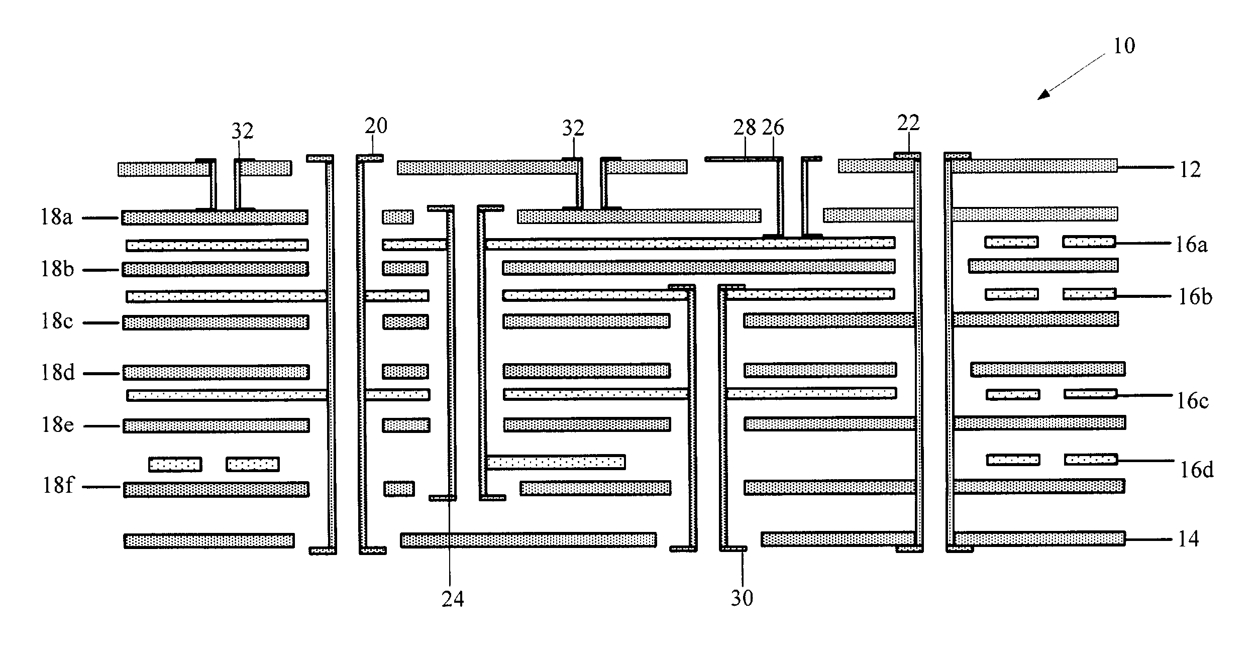
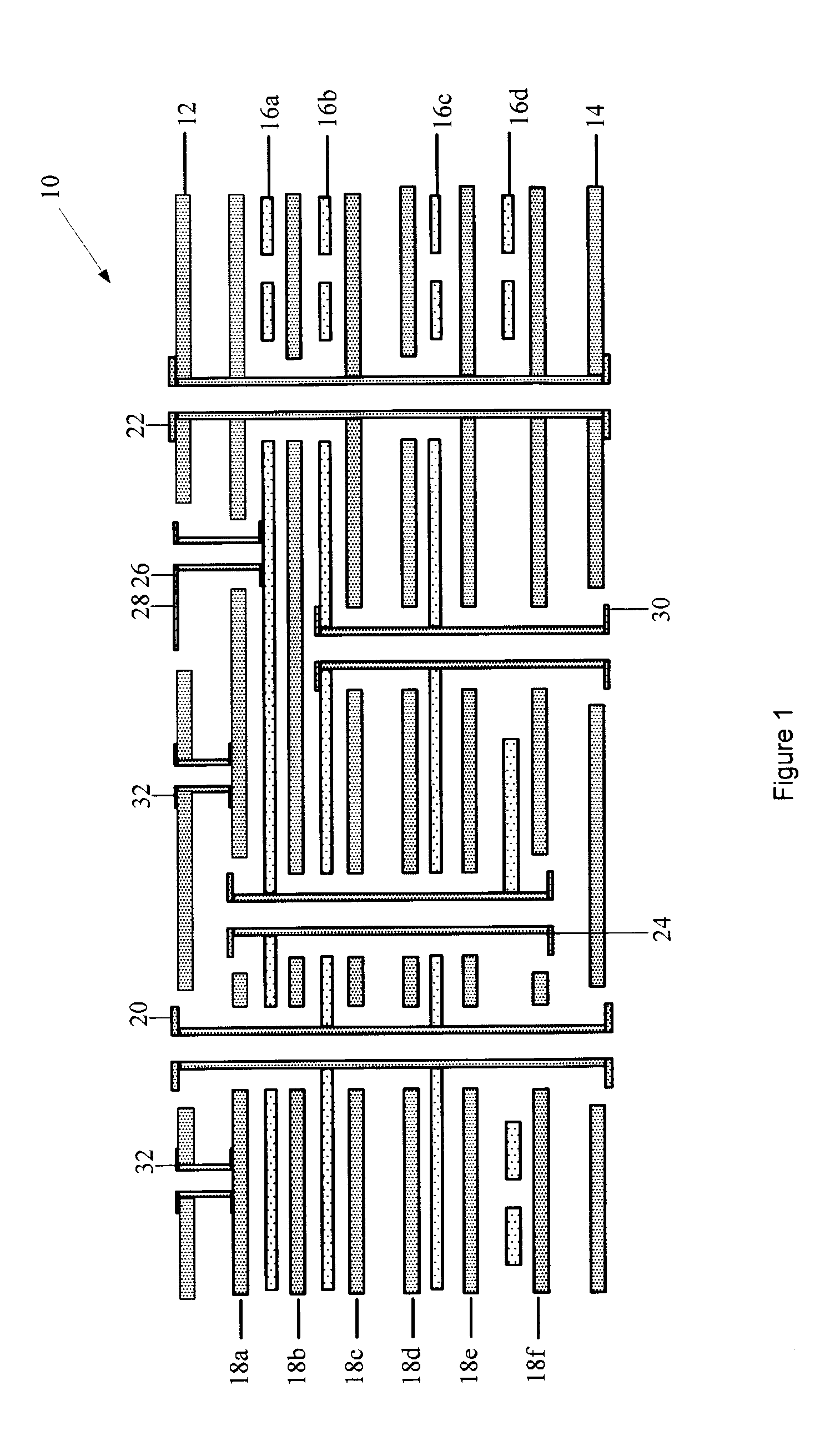
[0037]At the outset, it is helpful to refer to the microvia-based techniques for reducing the number of layers in a multilayer signal routing device and the power / ground-based techniques for reducing the number of layers in a multilayer signal routing device as have been substantially described in the above-referenced U.S. Provisional Patent Application No. 60 / 212,387, the above-referenced U.S. patent application Ser. No. 09 / 651,188 (now U.S. Pat. No. 6,388,890), the above-referenced U.S. patent application Ser. No. 10 / 101,211, the above-referenced U.S. patent application Ser. No. 10 / 126,700, the above-referenced U.S. patent application Ser. No. 10 / 326,123, and the above-referenced U.S. patent application Ser. No. 10 / 326,079, all of which have been incorporated by reference herein in their entirety.

[0038]The above-referenced microvia-based and power / ground-based techniques are certainly beneficial for reducing the number of layers in a multilayer signal routing device. However, the...


PUM

PropertyMeasurementUnit
Electrical conductivityaaaaaaaaaa
Electrical conductoraaaaaaaaaa
Efficiencyaaaaaaaaaa

Abstract

Techniques for reducing the number of layers in a multilayer signal routing device are disclosed. In one particular exemplary embodiment, the techniques may be realized as a method wherein the multilayer signal routing device has a plurality of electrically conductive signal path layers for routing a plurality of electrical signals thereon. The method may comprise forming a plurality of electrically conductive vias in the multilayer signal routing device for electrically connecting at least two of the plurality of electrically conductive signal path layers, wherein the plurality of vias are arranged so as to form at least one channel in at least one other of the plurality of electrically conductive signal path layers. The method may also comprise grouping at least a portion of the plurality of electrical signals based at least in part upon their proximity to the at least one channel so that they may be efficiently routed therein.

Description

CROSS-REFERENCE TO RELATED APPLICATIONS[0001]This patent application is a continuation-in-part patent application of U.S. patent application Ser. No. 10 / 126,700, filed Apr. 22, 2002 now U.S. Pat. No. 6,545,876, which is a continuation patent application of U.S. patent application Ser. No. 09 / 651,188, filed Aug. 30, 2000, now U.S. Pat. No. 6,388,890, which claims priority to U.S. Provisional Patent Application No. 60 / 212,387, filed Jun. 19, 2000, all of which are hereby incorporated by reference herein in their entirety.[0002]This patent application is also a continuation-in-part patent application of U.S. patent application Ser. No. 10 / 101,211, filed Mar. 20, 2002, which is a continuation-in-part patent application of the above-referenced U.S. patent application Ser. No. 09 / 651,188, filed Aug. 30, 2000, now U.S. Pat. No. 6,388,890, all of which are hereby incorporated by reference herein in their entirety.[0003]This patent application is also a continuation-in-part patent applicatio...

Claims


Application Information

Patent Timeline
IPC IPC(8): H05K3/36H05K1/00H05K3/46H05K1/11H05K3/00H05K3/42
CPCH05K1/115H05K1/112H05K1/0298Y10T29/49016H05K3/0005H05K3/429H05K3/4602H05K2201/09227H05K2201/09236H05K2201/09263H05K2201/09509H05K2201/09536H05K2201/09627H05K2201/10734Y10T29/49117Y10T29/49126Y10T29/49155Y10T29/49165F16L41/12
Inventor DUXBURY, GUY M. A. F.WYRZYKOWSKA, ANETADIFILIPPO, LUIGI G.KWONG, HERMAN
Owner RPX CLEARINGHOUSE
Why Eureka
Try Eureka