Cooling tank

a technology of cooling tank and water tank, which is applied in the field of cooling tank, can solve the problems of low cooling efficiency of cooling tank, difficulty in carrying both large-sized water tanks, and difficulty in assembling milk tanks for transportation, and achieves the effect of convenient dense loading and easy handling at loading

Inactive Publication Date: 2006-07-04
ROKKO ENG
View PDF7 Cites 8 Cited by
  • Summary
  • Abstract
  • Description
  • Claims
  • Application Information

AI Technical Summary

Benefits of technology

[0021]The cooling tank with such a structure is suitable for loading into transportation means, such as a ship, a track, and an airplane, being treated like a container to carry to a remote area. With assembled integrally, the cooling tank is easy to handle at loading to and unloading from transportation means and is convenient to be loaded densely on a carrier with stability. In addition, the reason that the cooling tank can be assembled into the structure suitable for loading or transportation is that, as described above, the cooling tank of the present invention can use a small-sized cooling unit.

Problems solved by technology

So it is hard to carry both a large-sized water tank, such as the water tank 34′, and the tank body simultaneously, and actually it is difficult to compose a milk tank to be mounted on a truck or the like for transportation.
The ice adhering to an evaporator will easily grow large, so the capacity of the water tank should be large enough to secure the quantity of the cooling water sent toward the tank body.b) The cooling tank has low cooling efficiency and its capacity to cool milk or the contents of the tank body is tend to be insufficient.
That is because the flow of the cooling water can hardly keep even velocity in the cooling jacket on the external peripheral surface of the tank body, and the stagnation often occurs in a wide area in the cooling jacket.
The difficulty of forming even velocity flow of the cooling water is caused by that the cooling jacket has no guide member therein for the cooling water which flows from the feed pipe to the return pipe, therefore the flow of the cooling water is not regulated.
Although the cooling capacity can be improved by increasing the flux of the cooling water or lowering the temperature of the cooling water, the cooling efficiency may not be improved because there still exist the areas where the cooling water cannot flow smoothly in the cooling jacket, and inconveniently the much larger-sized water tank is required.

Method used


Image

  • Cooling tank
  • Cooling tank
  • Cooling tank

Examples


Embodiment Construction

[0027]Referring to FIGS. 1–4, one preferred embodiment of the invention is hereafter described.

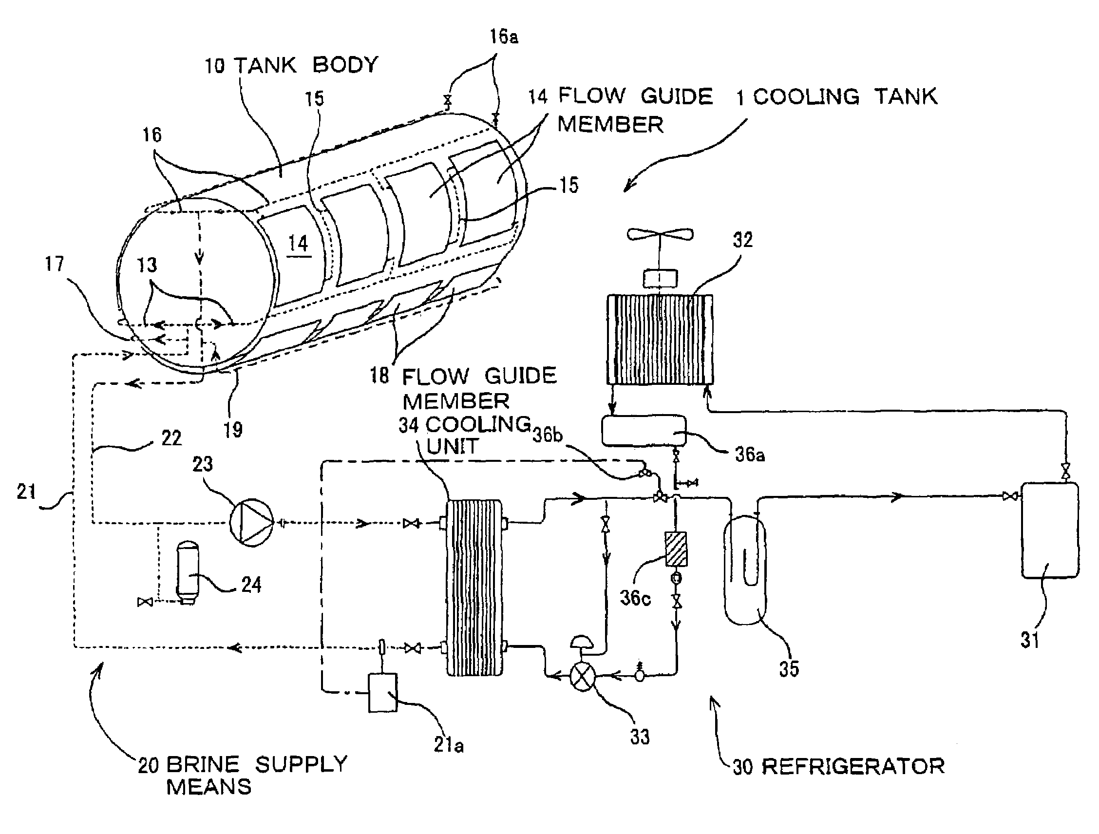
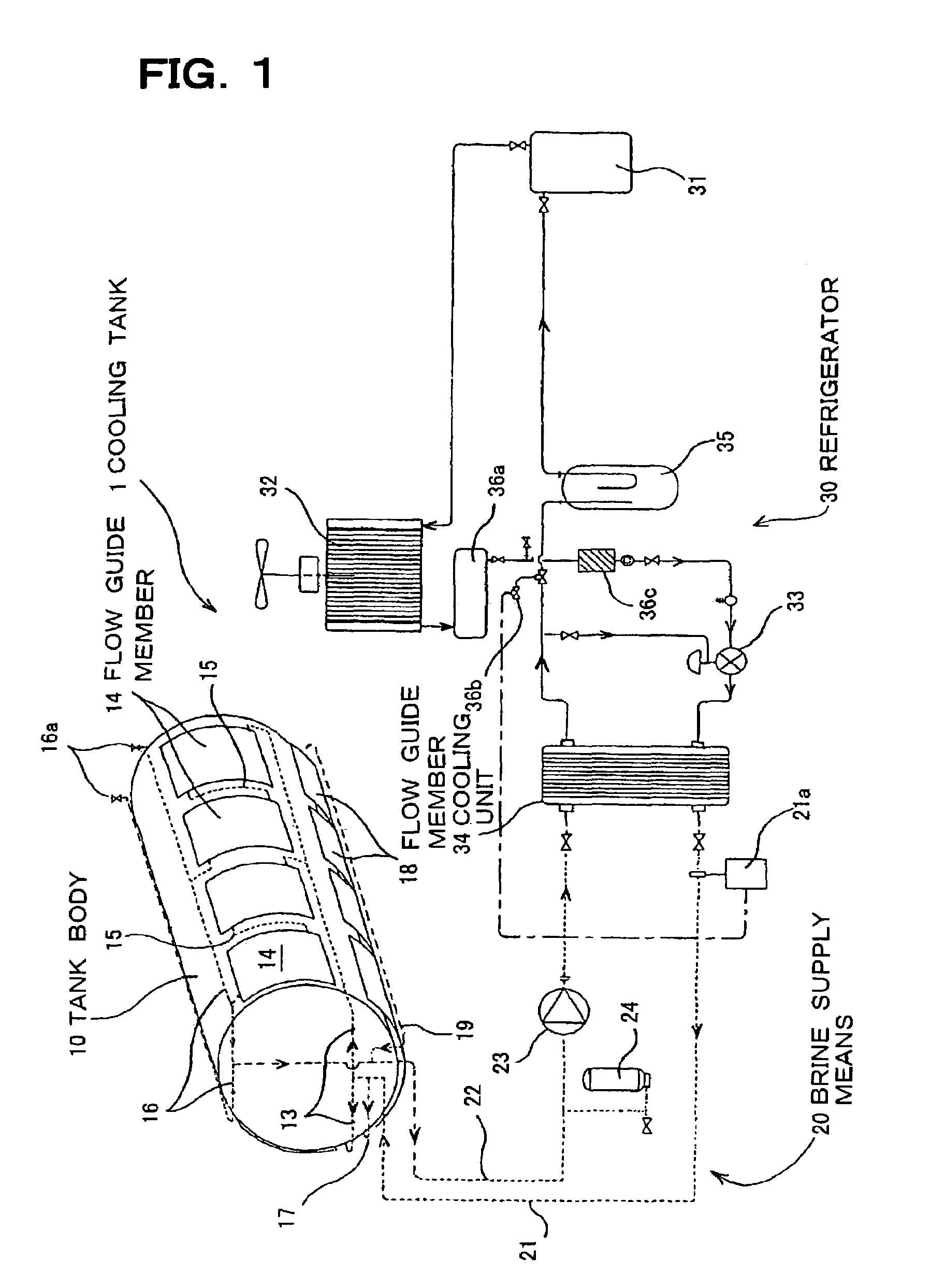
[0028]The cooling tank 1 shown in FIG. 1 is used for storing milk in the tank body 10 and maintaining the temperature of the milk around 0.degree. C. during transportation. The cooling tank 1 comprises the tank body 10 as a container of milk, the supply means 20 for the brine which cools the tank body 10 from the outside, and the refrigerator 30 for cooling the brine. The brine is cooled in a cooling unit (evaporator) 34 of the refrigerator 30 to about −1.degree. C. and cools the tank body 10 from its external surface. In addition, the tank body 10 must be equipped with basic compositions, such as an injection port and a take-out port for milk, and attached equipment for storage of milk.

[0029]The cooling tank 1 has the following features.

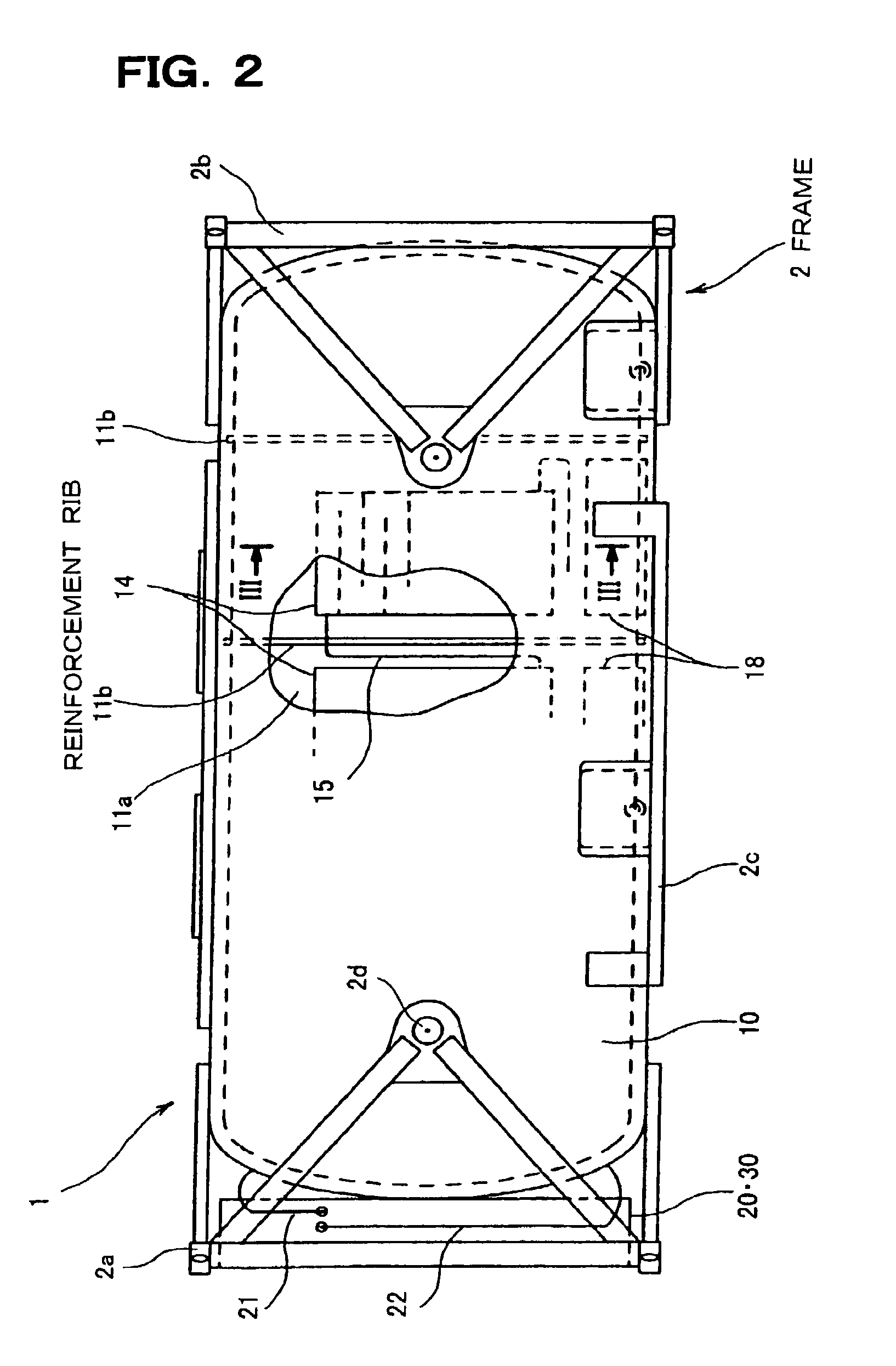
[0030]The first feature is that each component of the cooling tank 1 is assembled integrally into a frame 2, as shown in FIG. 2, so as to make it easy to ...


PUM

PropertyMeasurementUnit
freezing pointaaaaaaaaaa
storage temperatureaaaaaaaaaa
temperatureaaaaaaaaaa

Abstract

A tank is provided which can store, while cooling, drinks or other liquids, such as milk, having a storage temperature close to 0.degree. C. or below.
A cooling tank (1) can be mounted on a truck or the like for transportation, while storing and cooling milk. It is characterized in that brine (antifreeze solution) which has a freezing point below 0.degree. C. is cooled in a cooling unit (34) and allowed to pass, without stagnation, along fluid passages in flow guide members (14, 18) installed on the wall surface of the tank body (10). The cooling unit (34) preferably has an evaporator in a heat pump type refrigerator (30) for example, which uses a refrigerant for cooling the brine. Since the brine with a freezing point below 0.degree. C. is used, a large-sized water tank for cooling becomes unnecessary, and further since the brine will flow without stagnation, the liquid inside the tank body can be effectively cooled.

Description

TECHNICAL FIELD[0001]The present invention relates to a cooling tank for cooling and storage (and transportation, if necessary) of a liquid, especially milk or other drinks with a storage temperature close to 0.degree. C. or below.BACKGROUND ART[0002]A milk tank for storing milk is desired to have a cooling function in order to keep milk fresh. A milk tank with a cooling function is disclosed in the Japanese Patent Laid Open Gazette Hei. 7-8127 for example.[0003]The milk tank described in the gazette comprises a tank body 10′, a water tank (ice bank) 34′ and a refrigerator 30′, which are connected by a pipe 21′ or the like as shown in FIG. 5. In other words, an evaporator 34a′ which allows the refrigerant of the refrigerator 30′ pass through is placed inside the water tank 34′ where the cooling water is cooled to nearly 0.degree. C., and the cooling water is circulated through a cooling jacket 14′ which is provided on the external peripheral surface of the tank body 10′ by means of ...

Claims


Application Information

Patent Timeline
Patent Type & Authority Patents(United States)
IPC IPC(8): F25D17/02A01J9/04A01J13/00A23C3/04A23L3/36B60P3/22B65D88/12B65D88/74B65D90/02B65D90/06C12C7/26F25D31/00
CPCA01J9/04B60P3/2295B65D88/128F25D31/006B65D88/748B65D90/022B65D88/744F25D17/02Y02A40/963Y02P60/87
Inventor OMUTA, MAMORUTABUCHI, OSAMULI, JUNG CHUN
Owner ROKKO ENG
Why Eureka
Try Eureka