
Suture reel dispenser with end of suture indicator

a dispenser and suture technology, applied in the direction of transportation and packaging, tray containers, rigid containers, etc., can solve the problems of increasing the risk of intraoperative and postoperative complications, increasing the risk of wasting sterile instruments and equipment, and increasing the risk of patients remaining anesthetized for longer than is necessary, so as to reduce the time in the operating room, increase patient safety, and reduce the cost of surgery

Inactive Publication Date: 2006-07-04
ROSENFELD DAVID
View PDF18 Cites 28 Cited by
  • Summary
  • Abstract
  • Description
  • Claims
  • Application Information

AI Technical Summary

Benefits of technology

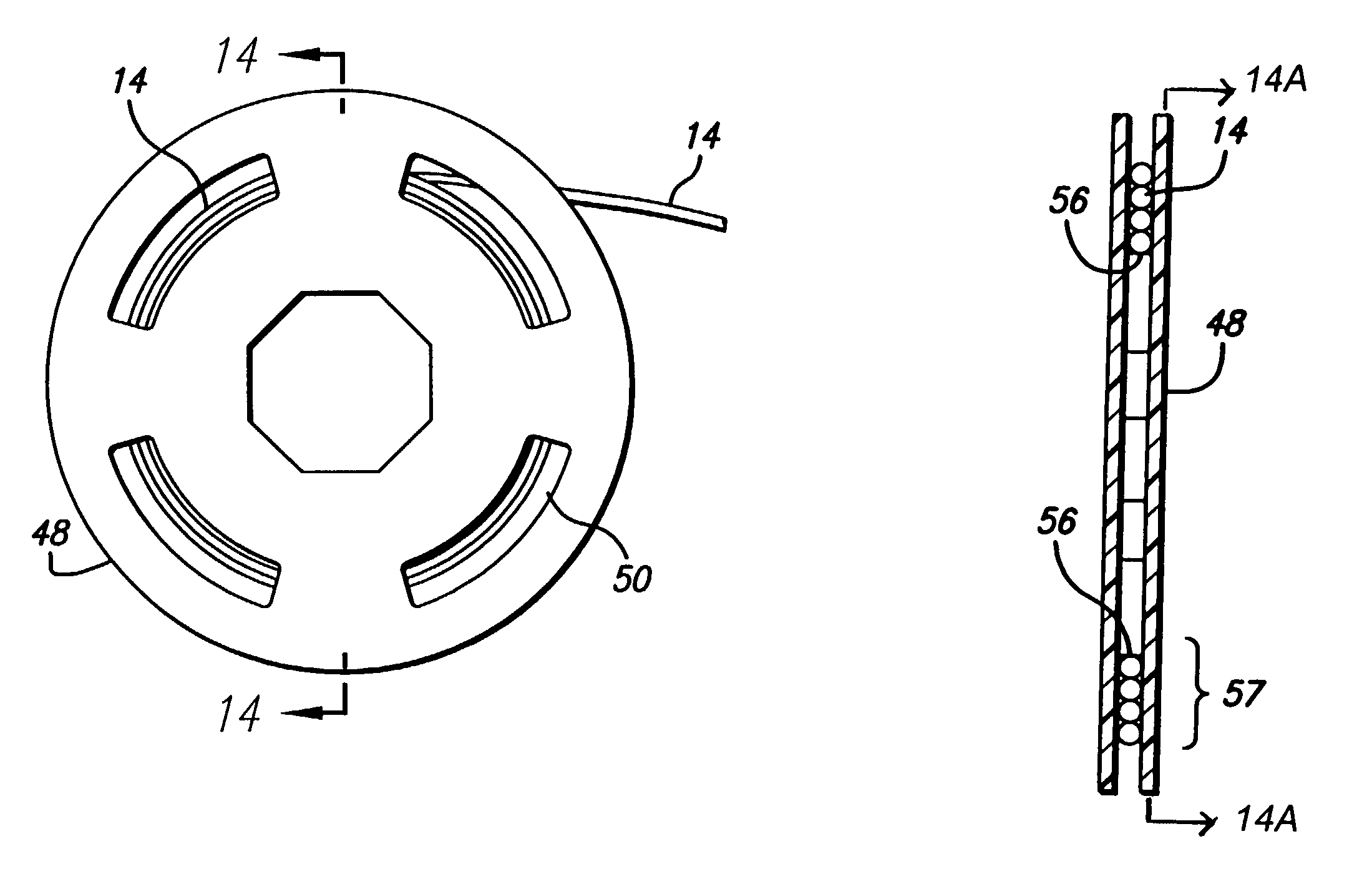
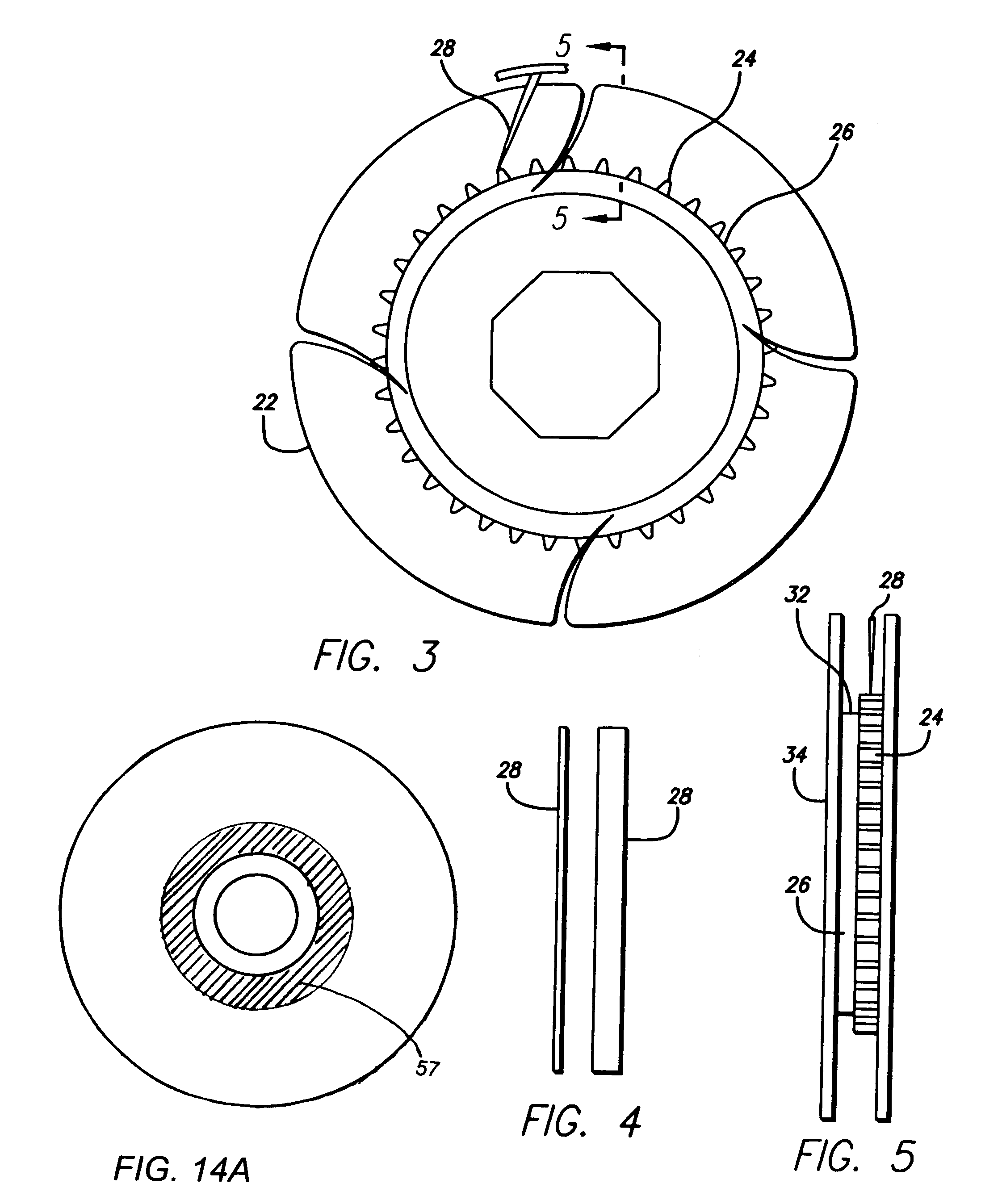
"The present invention provides a suture reel dispenser mechanism that includes visual, auditory, and vibratory indicia to alert the surgeon when the end of the suture reel is near. This allows the surgeon to easily determine when they are approaching the end of their suture supply and quickly call for another reel. The indicia can be embedded in the suture or applied to the suture reel, making it easy for the surgeon to see and respond to. The suture reel is designed to accommodate the specific diameter of the suture, and a view window is included to allow the surgeon to observe the remaining amount of useable suture on the reel and easily approximate when the wound suture will be coming to its end. This invention provides a reliable and easy-to-use suture reel dispenser mechanism that helps surgeons manage their suture supply more effectively and reduces delays in obtaining more suture."

Problems solved by technology

For surgeons, an emphasis on working safely and quickly in the operating theatre is of paramount importance, as extra time spent during surgery can be dangerous to the patient.
A patient remaining anesthetized for longer than is necessary endures more intraoperative and postoperative risks, including: atelectasis (lung collapse) which can lead to pneumonia, deep venous thrombosis (clots in the veins of the legs), pulmonary embolism (clots that leave the veins of the legs and lodge in the lung veins), stroke, myocardial infarction (heart attack), and even death.
Wasting sterile instruments and equipment can be quite expensive.
These delays can be very lengthy.
A major disadvantage of prior suture and reel dispensers, is that the surgeon never knows how many ties he or she will have per reel so that he or she does not know when the suture will end until the last piece of useable suture is pulled out of the reel.
Very often, the surgeon is left holding a piece of suture, which is too short to use.
The surgeon must then ask for another suture reel, which often results in an unacceptable delay before another sterile reel is available for the surgeon.
This delay can be detrimental to the patient's health.
Since it is never really known how much suture will be used during any individual operation; and, since any exposed, but, unused suture must be disposed of, this wasted material adds up to an increase in the cost of health care.
This concept, in actuality, is not feasible for several reasons.
In order to observe the suture winding down, the surgeon would have to continuously look at the suture reel when pulling the suture out of the suture reel dispenser; by which action, would take the focus of the surgeon off the operation and, therefore, would be unacceptable.
Another disadvantage of the prior suture reel dispenser is difficulty in handling it.
The apparatus is quite small, which makes it difficult to hold the suture reel dispenser without the surgeon's fingers touching the suture reel.
Moreover, surgeons wear gloves, which makes this task even more arduous.
Friction on the suture reel from the surgeon's fingers both increases the force necessary to pull the suture out of the suture reel dispenser and prevents the suture reel from turning freely.
For example, at times, while the surgeon is pulling suture from the dispenser, the whole apparatus can become dislodged from the surgeon's grasp, caused by an abrupt stopping force or tension, when the suture reel does not rotate smoothly.
Any disruption of a normal, smooth dispensing action of the suture, results in the surgeon's attention being diverted away from the operating field; thereby causing an unacceptable delay and is, most always, quite frustrating to the surgeon.
Lastly, another disadvantage of prior suture reel dispensers is that some suture needs to be moist, however, housing mechanisms are developed to house dry suture.
Liquid can be placed into the housing but there is no guarantee that this will continuously be in contact with the suture.

Method used


Image

  • Suture reel dispenser with end of suture indicator
  • Suture reel dispenser with end of suture indicator
  • Suture reel dispenser with end of suture indicator

Examples


Embodiment Construction

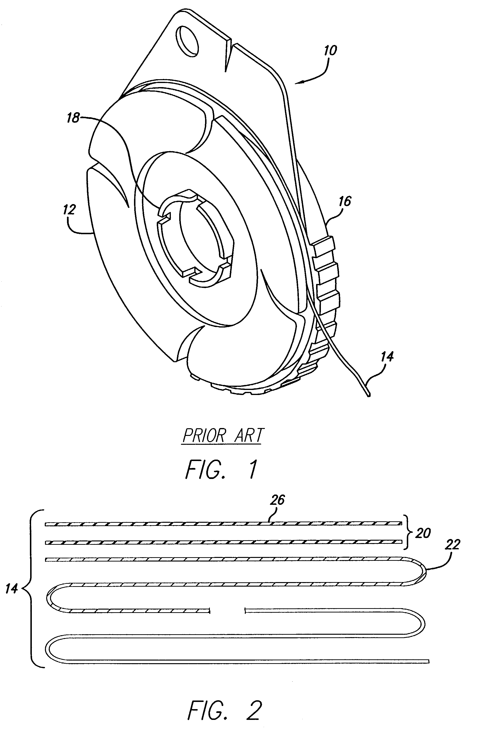
[0058]Referring to FIG. 1, a typical prior art suture reel dispenser is indicated at 10 and contains the suture reel 12, suture 14, and suture reel housing 16. The suture reel 12 sits within the suture reel housing 16 and rotates upon a boss 18 also contained within and attached to the suture reel housing 16. The suture 14 is loaded onto the suture reel 12 and when pulled unwinds from the suture reel 12 as it rotates on the boss 18.

[0059]Referring to FIG. 2, an end portion 20 the suture 14 is marked with visual indicia 22 of a different appearance with respect to the major portion of the suture 14 which has been previously unwound from the suture reel 12. The difference in appearance can be based on a pattern that is solid, alternating vertical, alternating diagonal, striped, alternating dotted, hatched or a combination of any pattern including ones not listed above. More than one pattern can be used. The combination of patterns can be mixed with one another, or placed sequentially ...


PUM


Abstract

A dispenser for suture, including a suture reel on which the suture is mounted and an indicator that the suture is soon to be depleted. The indicator can be a visual marking on the suture, or it can be an audible and / or vibratory effect obtained by the dispenser housing interacting with the suture through one or more view ports or by interaction of a follower cam with the reel structure as the suture becomes depleted.

Description

CROSS REFERENCE TO RELATED APPLICATIONS[0001]This application is a divisional of application Ser. No. 09 / 576,980 filed May 23, 2000, now U.S. Pat. No. 6,467,612 and claims the benefit of Provisional Patent Application Nos. 60 / 135,465, filed May 24, 1999 and 60 / 143,794, filed Jul. 14, 1999, and 60 / 143,795, filed Jul. 14, 1999.FIELD OF THE INVENTION[0002]The field of the invention relates to suture reel dispensers and suture.BACKGROUND OF THE INVENTION[0003]For surgeons, an emphasis on working safely and quickly in the operating theatre is of paramount importance, as extra time spent during surgery can be dangerous to the patient. A patient remaining anesthetized for longer than is necessary endures more intraoperative and postoperative risks, including: atelectasis (lung collapse) which can lead to pneumonia, deep venous thrombosis (clots in the veins of the legs), pulmonary embolism (clots that leave the veins of the legs and lodge in the lung veins), stroke, myocardial infarction (...

Claims


Application Information

Patent Timeline
Patent Type & Authority Patents(United States)
IPC IPC(8): A61B17/06
CPCA61B17/06123
Inventor ROSENFELD, DAVID
Owner ROSENFELD DAVID
Learn More