Mount assembly

a technology of mounting brackets and mounting brackets, which is applied in the direction of roofs, machine supports, other domestic objects, etc., can solve the problems of inability to control the nature and location of the transition from soft to hard spring rates, the height of the mounting bracket is not easily adjustable, and the maximum displacement of the mounting bracket is sometimes still too large. , to achieve the effect of low maximum displacement, easy tunable or customizable, and reasonable heigh

Inactive Publication Date: 2006-07-04
BASF CORP
View PDF16 Cites 42 Cited by
  • Summary
  • Abstract
  • Description
  • Claims
  • Application Information

AI Technical Summary

Benefits of technology

[0010]A mount assembly for use with a vehicle having a frame. The assembly comprises a carrier having a peripheral outer rim. The carrier is adapted to be mounted to the frame of the vehicle. An insulator is adapted to be coupled to the frame of the vehicle and extends beyond the peripheral outer rim. The carrier is formed of a polyurethane elastomer having a first modulus of elasticity. The insulator is formed of a microcellular polyurethane having a second modulus of elasticity that is less than the first modulus of elasticity of the carrier such that the mount assembly can provide two distinct rates of elasticity for adequately isolating both low amplitude, high frequency vibrations and high amplitude, low frequency impacts.

Problems solved by technology

Although, these MPU insulators can provide the soft spring rate as well as some maximum displacement control, the total maximum displacement is sometimes still too large and the nature and location of the transition from soft to hard spring rate cannot be controlled independent of the properties of polymer.
Thus these types of insulators are not easily tunable.
Also, soft insulators, such as MPU, can have a relatively large height, which require large clearances between the carrier and the frame.
This also creates an undesirable large displacement between the carrier and the frame during translational motion which equates to an undesirable large movement (maximum displacement) between the frame and the vehicle body.
Further, MPU is more difficult to mold and thus provides limited choices of geometry.
However, the conventional insulators still have significant limitations and typically cannot be adequately customized or tuned.

Method used


Image

  • Mount assembly
  • Mount assembly
  • Mount assembly

Examples


first embodiment

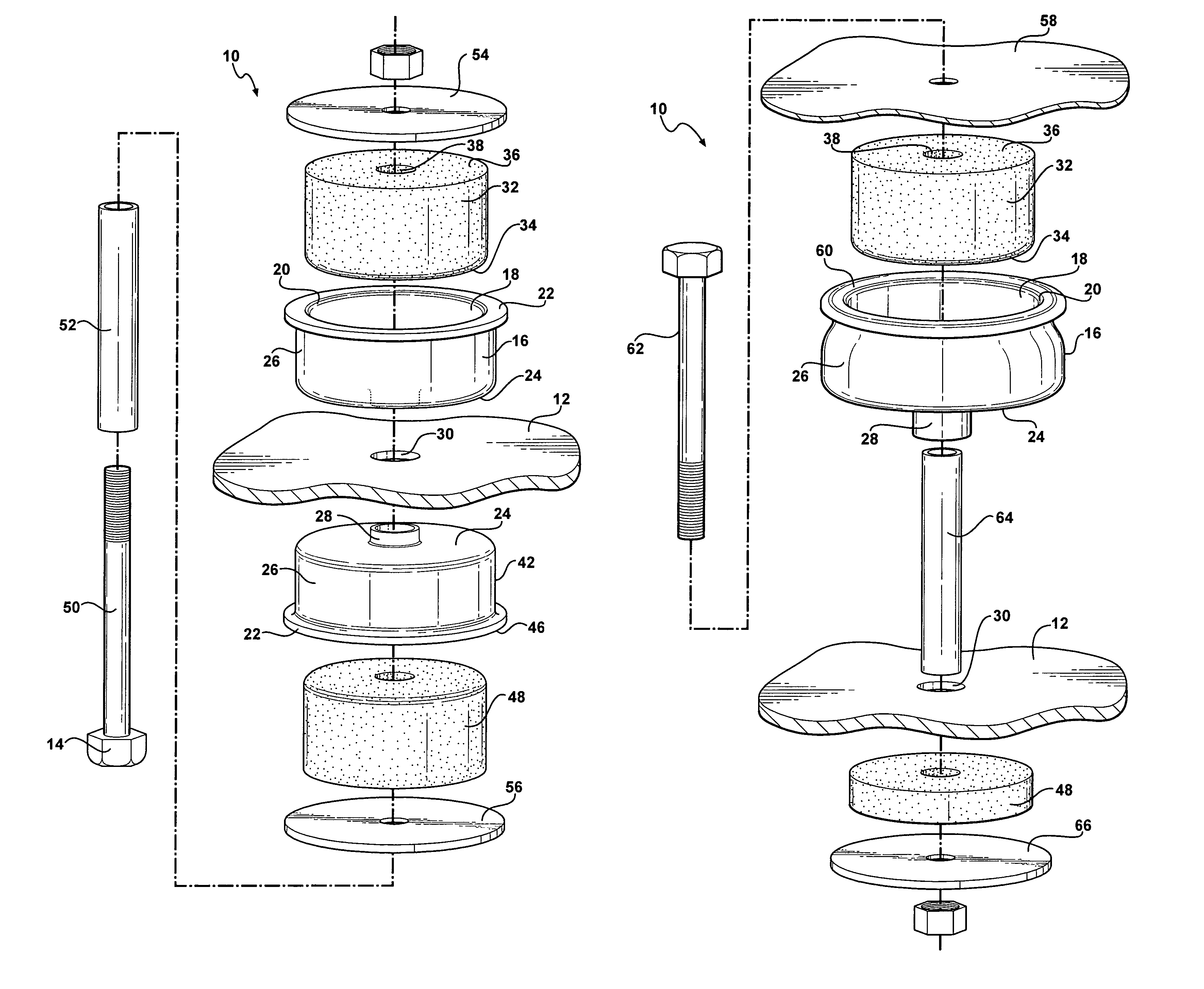
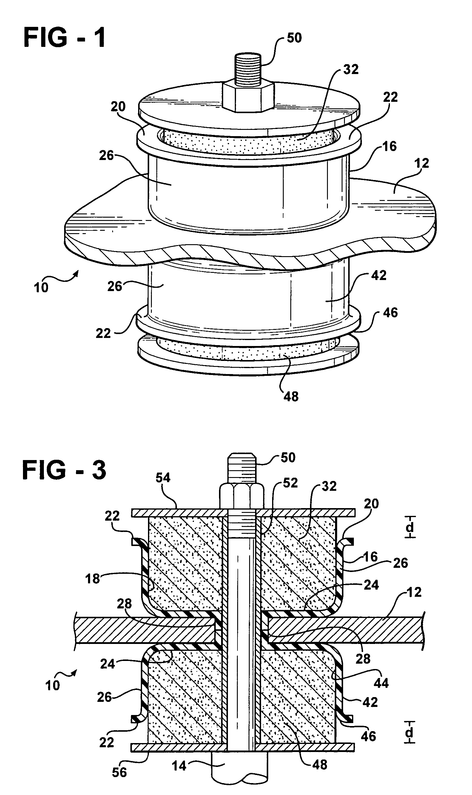
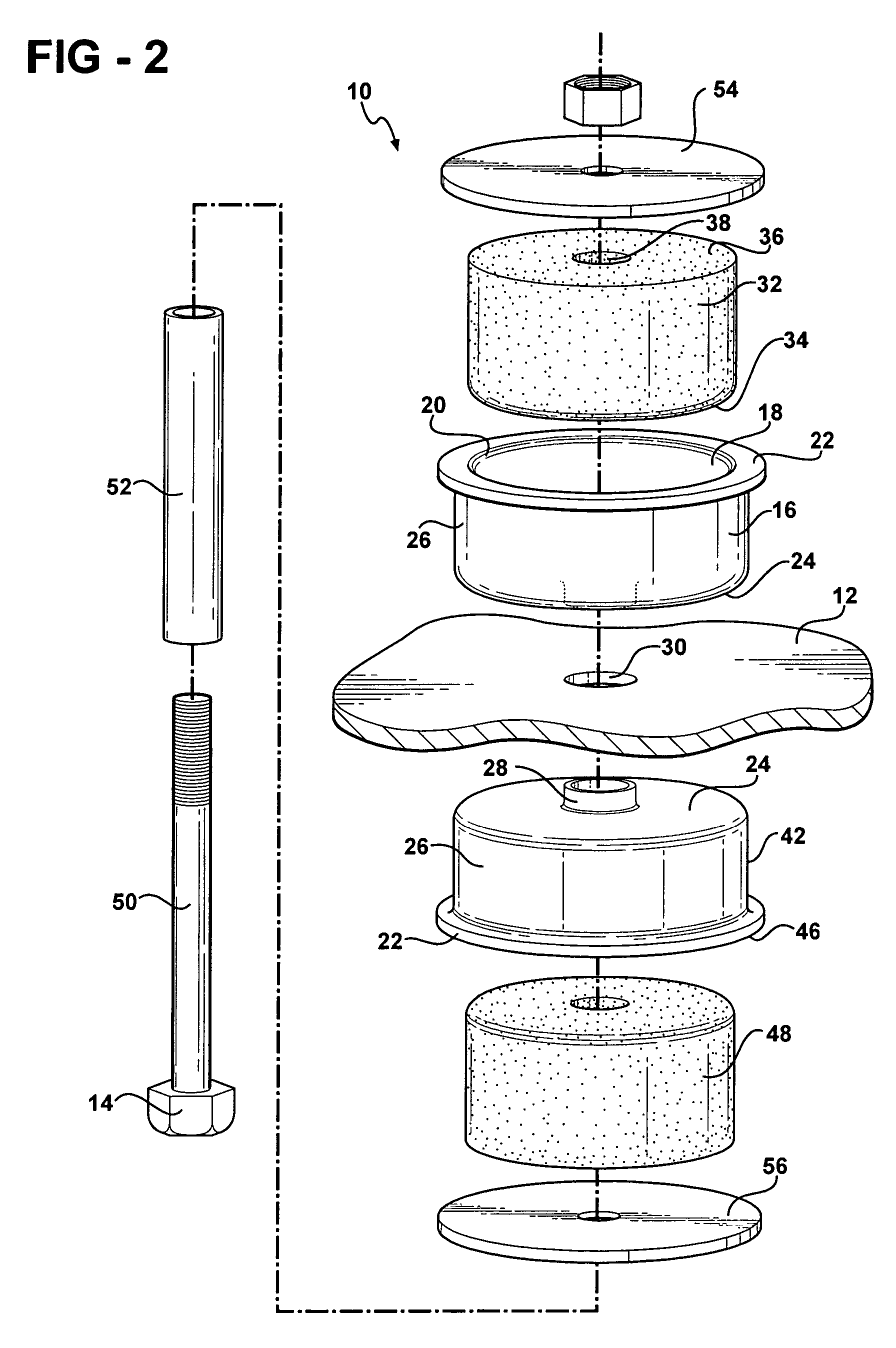
[0032]Similarly, the insulator 32 is further defined as a first insulator 32 and the first embodiment also includes a second insulator 48. The second insulator 48 is disposed within the second inner cavity 44 of the second carrier 42 and extends beyond the second peripheral outer rim 46 of the second carrier 42 in a similar fashion as the first insulator 32 within the first carrier 16.

[0033]The second carrier 42 is formed of a polyurethane elastomer having a third modulus of elasticity with the material properties in the same range as the first carrier 16. Preferably, the second carrier 42 is also formed of a homogenous polyurethane elastomer having a substantially uniform thickness. The second insulator 48 is formed of a microcellular polyurethane having a fourth modulus of elasticity that is less than the third modulus of elasticity of the second carrier 42. The first and third modulus of elasticity are substantially identical. Further, the second and fourth modulus of elasticity ...

second embodiment

[0039]The mount assembly 10 of this second embodiment also includes a carrier 16 preferably having a substantially cup shaped configuration defining an inner cavity 18 and a peripheral outer rim 20. Even more preferably, the peripheral outer rim 20 of the carrier 16 is continuous and substantially circular to form a substantially circular cavity 18 within the carrier 16. In this embodiment, however, the peripheral outer rim 20 of the carrier 16 preferably includes a curled distal end 60 curling outwardly away from the cavity 18. The cup shaped carrier 16 includes a substantially flat bottom 24 and a substantially upstanding wall 26 extending between the peripheral outer rim 20 and the flat bottom 24 to further define the cavity 18 within the carrier 16. The flat bottom 24 of the carrier 16 defines an opening and the carrier 16 further includes a second wall 28 surrounding the opening and extending in a direction opposite to the upstanding wall 26.

[0040]The carrier 16 is adapted to b...

third embodiment

[0057]Another advantage of using the elastomeric polyurethane, such as thermoplastic or thermoset polyurethane, and microcellular polyurethane is that these materials are readily bondable using urethane glues, as is well known in the art. As such, the microcellular polyurethane insulator 32 could be bonded within the inner cavity 18 of the elastomeric polyurethane carrier 16. FIG. 9A illustrates an enlarged sectional view of the insulator 32 and carrier 16 of this third embodiment, which shows a layer of urethane glue 40 bonding the insulator 32 to the carrier 16. This ability to bond allows for an integrated composite mount assembly 10 without any additional fastening means.

[0058]As shown in FIG. 9, the strike plate 68 can move to abut the insulator 32 and then compress the insulator 32 through a distance (d) relative to the vehicle body 58, which isolates the vehicle body 58 from the strike plate 68. As the strike plate 68 continues to compress the insulator 32 beyond the distance...


PUM


Abstract

A mount assembly for use in an automotive suspension system, body mount, cradle mount, or other like device. The mount assembly includes a polyurethane elastomer carrier mounted to a frame and having a peripheral outer rim. A microcellular polyurethane insulator is coupled to the frame and extends beyond the peripheral outer rim. The polyurethane elastomer of the carrier has a first modulus of elasticity. The microcellular polyurethane of the insulator has a second modulus of elasticity that is less than the first modulus of elasticity of the carrier such that the mount assembly can provide two distinct rates of elasticity, or stiffness, for adequately isolating both low amplitude, high frequency vibrations and high amplitude, low frequency impacts.

Description

BACKGROUND OF THE INVENTION[0001]1. Field of the Invention[0002]The subject invention relates to a mount assembly for a vehicle wherein the mount assembly isolates vibrational and / or translational movements between a frame of the vehicle and a vehicle body.[0003]2. Description of Related Art[0004]Mount assemblies for vehicles are well known in the art. Examples of such assemblies are shown in U.S. Pat. Nos. 5,799,930 and 6,361,096. Each of these assemblies include a steel carrier having one or more insulators. The carrier and insulators are mounted between a frame of a vehicle and a vehicle body in order to isolate movement between the frame and vehicle body. The insulators are typically formed of an elastomeric material such as rubber or microcellular polyurethane (MPU).[0005]The stiffness of the insulator is based on material stiffness (modulus of elasticity) and geometry. As such, one important factor in the development of mount assemblies relates to the modulus of elasticity, al...

Claims


Application Information

Patent Timeline
Patent Type & Authority Patents(United States)
IPC IPC(8): F16M13/00F16F1/37F16F1/371F16F3/093
CPCF16F1/37F16F3/093F16F1/3713
Inventor HUPRIKAR, ANANDST. HENRY, TOM
Owner BASF CORP
Why Eureka
Try Eureka