Connector for connecting printed boards

a technology for connecting printed boards and connecting cables, applied in the direction of coupling device connections, coupling device details, coupling protective earth/shielding arrangements, etc., can solve the problems of increasing the pitch of the connector, increasing the size of the connector, and increasing the cost of the connector

Active Publication Date: 2006-07-04
JAPAN AVIATION ELECTRONICS IND LTD
View PDF14 Cites 21 Cited by
  • Summary
  • Abstract
  • Description
  • Claims
  • Application Information

AI Technical Summary

Benefits of technology

[0011]It is another object of the present invention to provide a cheaply manufactured connector able to match impedance in the connector without changing the pitch of a soldering portion as a terminal portion of the contact.
[0018]According to the present invention, there is provided a connector in which pitch interval between the contact portions of the pair of signal contacts is set to be narrower than the pitch interval between the terminal portions by widening the width of the contact portion of each signal contact toward the signal contact side instead of the construction in which the contact portion of each of the pair of signal contacts approaches.

Problems solved by technology

Therefore, there is a defect in that the connector is large-sized.
However, a useless terminal or contact is correspondingly inserted so that there is a defect in that the connector becomes expensive.
There is a defect in that the pitch of the connector is increased and the size of the connector itself is increased when the electric characteristics are preferentially set.
Further, there is a defect in that no electric characteristics are matched when the pitch is reversely preferentially reduced.

Method used


Image

  • Connector for connecting printed boards
  • Connector for connecting printed boards
  • Connector for connecting printed boards

Examples


first embodiment

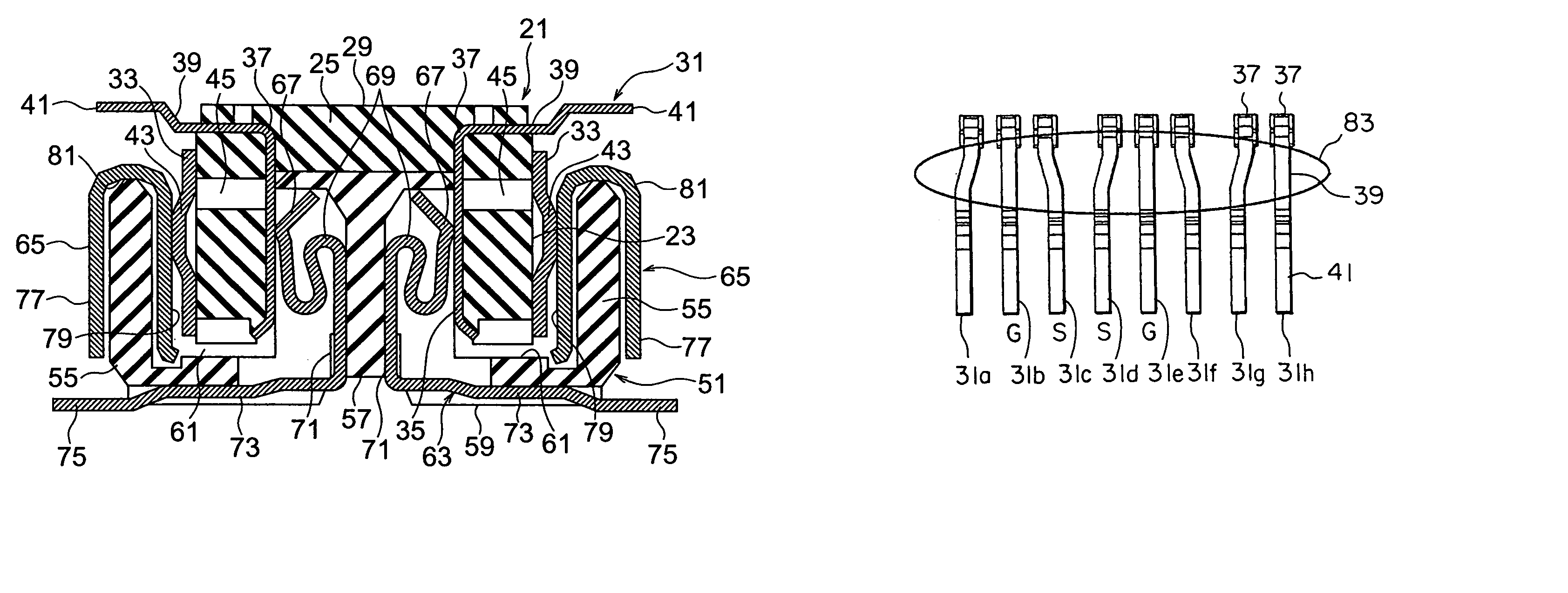
[0055]Concretely, in the plug contact 31 in the present invention, the support portion 39 is slantingly bent on the right-hand side with respect to the third direction as the direction perpendicular to the pitch direction of the contact about contacts 31a, 31d, 31g, and is slantingly bent on the left-hand side with respect to the third direction about contacts 31c, 31f. Thus, the pitch between the contact portions 37 of the respective contacts 31 is changed and the pitch is increased in the direction separated from each other with respect to the contact portions 37 of signal contacts 31a, 31c, 31d, 31g. In contrast to this, a pitch converting portion 83 formed so as to narrow the pitch is arranged with respect to ground contacts 31b, 31e, 31h about the contact portions 37 of the signal contacts 31a, 31c, 31d, 31g.

[0056]Thus, impedance can be matched.

[0057]Referring to FIGS. 7 and 8, receptacle contacts 63 are mutually symmetrically arranged in two columns in the width direction. Fo...

second embodiment

[0063]In the plug contact in accordance with the present invention, the support portion 39 is slantingly bent on the right-hand side with respect to the third direction equal to the extending direction of the contact and perpendicular to the first and second directions about the contact 87c, and is slantingly bent on the left-hand side with respect to the third direction about the contact 87d. Thus, the pitch between the contact portions 37 of the respective contacts 87 is changed, and the pitch is reduced in the direction approaching each other with respect to the contact portions 37 of the signal contacts 87c, 87d. In contrast to this, a pitch converting portion 89 formed so as to widen the pitch is arranged with respect to the ground contacts 87b, 87e about the contact portions 37 of the signal contacts 87c, 87d. Thus, impedance can be controlled and matched.

[0064]Referring to FIGS. 11 and 12, receptacle contacts 91 are arranged in parallel with the second direction perpendicular...

third embodiment

[0070]Concretely, in the plug contact 93 in the present invention, the contact portion 37 is eccentrically formed so as to be widened on the right-hand side in the third direction perpendicular to the first and second directions with respect to the contact portion 37b of the contact 93c, and is eccentrically formed so as to be widened on the left-hand side in the third direction with respect to the contact portion 37c of the contact 93d. Thus, the pitch between the contact portions 37 of the respective contacts 93 is changed, and the pitch is reduced in the direction approaching each other with respect to the contact portions 37c, 37d of the signal contacts 93c, 93d. In contrast to this, a pitch converting portion 16 formed so as to widen the pitch is arranged with respect to the contact portions 37a of the ground contacts 93b, 93e about the contact portions 37c, 37d of the signal contacts 93c, 93d. Thus, impedance can be controlled and matched.

[0071]Referring to FIGS. 15 and 16, re...


PUM


Abstract

In a connector, a contact group has a signal contact and a ground contact, and the signal contact is arranged adjacently to both sides of the ground contact. Each of the signal contact and the ground contact has a contact portion connected to a partner side contact and also has a terminal portion connected to a connecting object. The pitch intervals between the terminal portions of the respective contacts of the contact group are equally set. The contact portion of the signal contact approaches the contact portion of the ground contact. Thus, the pitch interval between the contact portions of the adjacent signal contacts is widened with respect to the pitch interval between the terminal portions.

Description

[0001]This application claims priority to prior Japanese patent application JP 2003-381853, the disclosure of which is incorporated herein by reference.BACKGROUND OF THE INVENTION[0002]The present invention relates to a connector requiring impedance matching for electric characteristics, e.g., an increase in speed of LVDS, TMDS, PCI express transmission, etc., and more particularly relates to a connector having a joining portion joined to a substrate by soldering, etc., and a fitting portion coming in contact with a partner side connector, FPC or PCB.[0003]A connector is shown in Japanese Patent Application Publication (JP-A) No. 2001-511300 (corresp. to WO98 / 35408), hereinafter called Reference 1, as the connector for connecting substrates to each other. The connector shown in Reference 1 is a connector for connecting two substrates so as to be perpendicular to each other and has a large-sized structure.[0004]A socket connector and a plug connector are arranged in each of the mutua...

Claims


Application Information

Patent Timeline
Patent Type & Authority Patents(United States)
IPC IPC(8): H01R12/00H01R24/00H01R13/648H01R43/20
CPCH01R13/6471H01R13/6474H01R13/6582H01R12/73Y10S439/941H01R24/70
Inventor OBIKANE, HIROAKIHAYASHI, KOJISUZUKI, MAMORUKATO, NOBUKAZU
Owner JAPAN AVIATION ELECTRONICS IND LTD
Why Eureka
Try Eureka