Coaxial cable insulation displacement connector

a technology of displacement connector and coaxial cable, which is applied in the direction of two-pole connection, contact member penetrating/cutting insulation/cable strand, coupling device connection, etc., can solve the problems of increasing the number of components, time-consuming and often hazardous procedures, and damage the connection between the connector and the cable, so as to reduce the size of the connector and reduce the number of components , the effect of faster termination of coaxial cables

Inactive Publication Date: 2006-07-04
YAZAKI NORTH AMERICA
View PDF11 Cites 24 Cited by
  • Summary
  • Abstract
  • Description
  • Claims
  • Application Information

AI Technical Summary

Benefits of technology

[0014]The invention enables the size of the connector to be reduced. It allows use of an insulation displacement termination method for faster termination of coaxial cable...

Problems solved by technology

This can eliminate the need to significantly bend the cable, and thereby possibly damage the connection between the connector and cable, when making the electrical engagement.
However, this procedure is time consuming and often hazardous.
One requires two contacts, resulting in increased component count.
The other requires only one contact, but the cable has to be b...

Method used


Image

  • Coaxial cable insulation displacement connector
  • Coaxial cable insulation displacement connector
  • Coaxial cable insulation displacement connector

Examples


Embodiment Construction

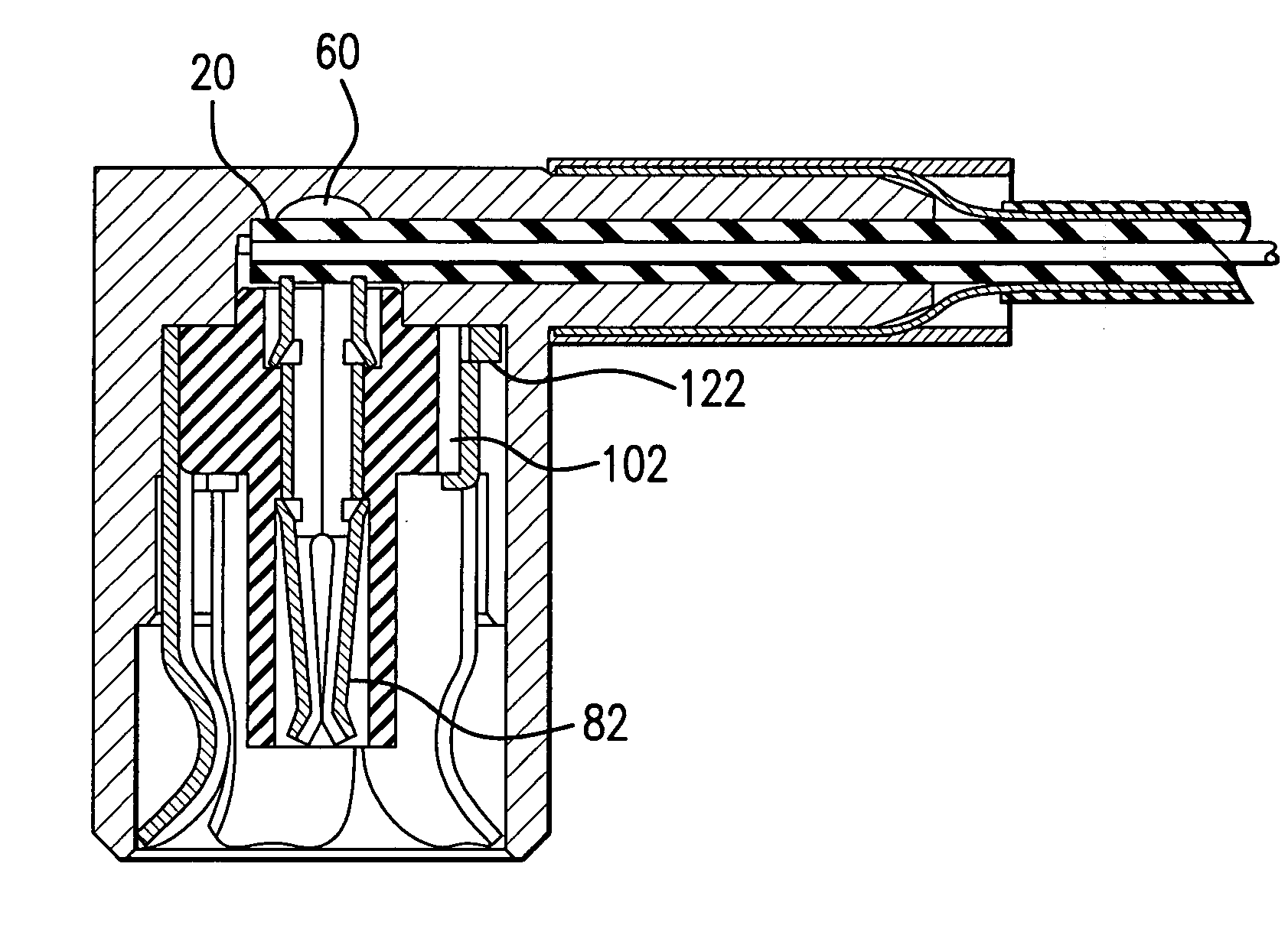
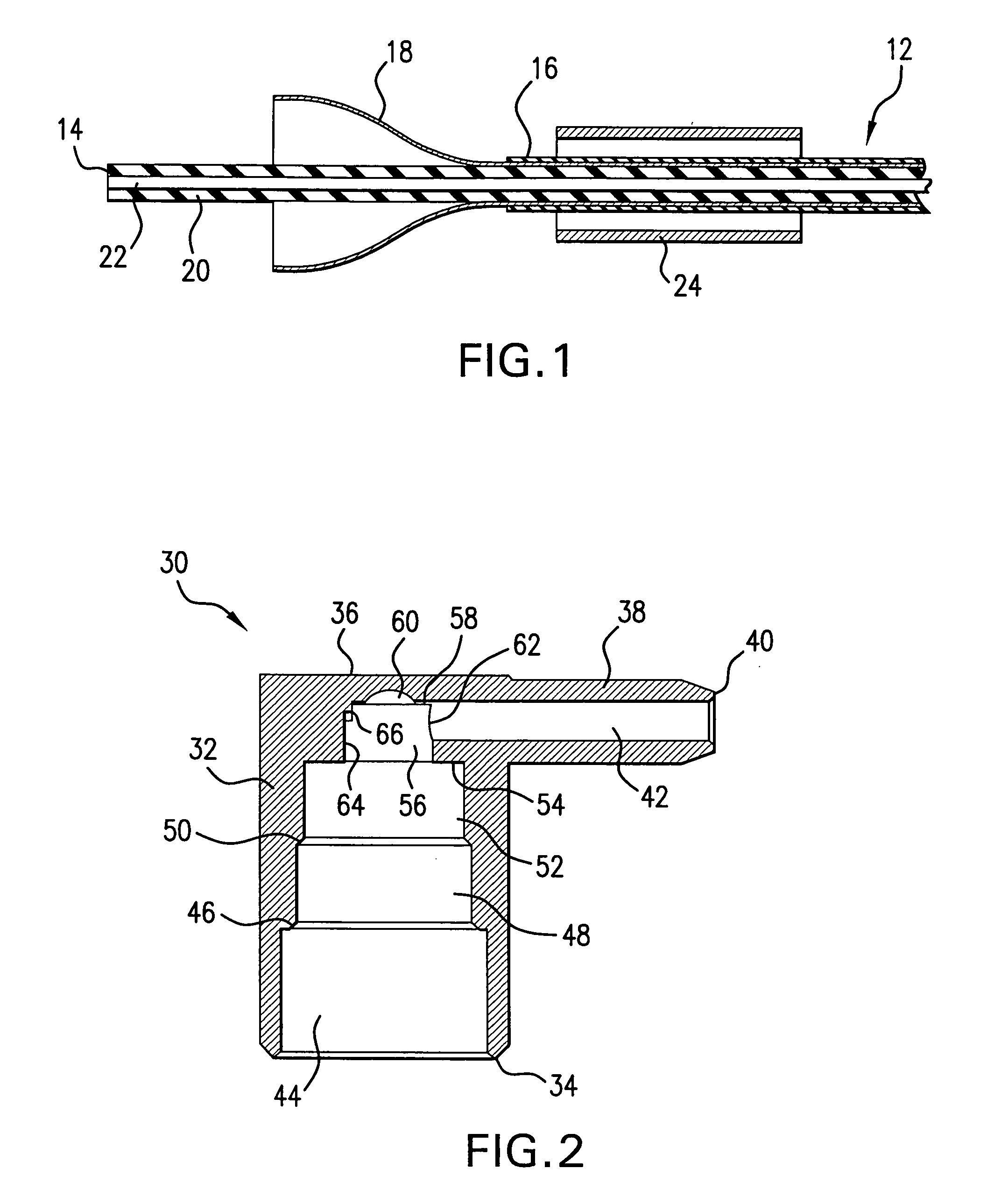
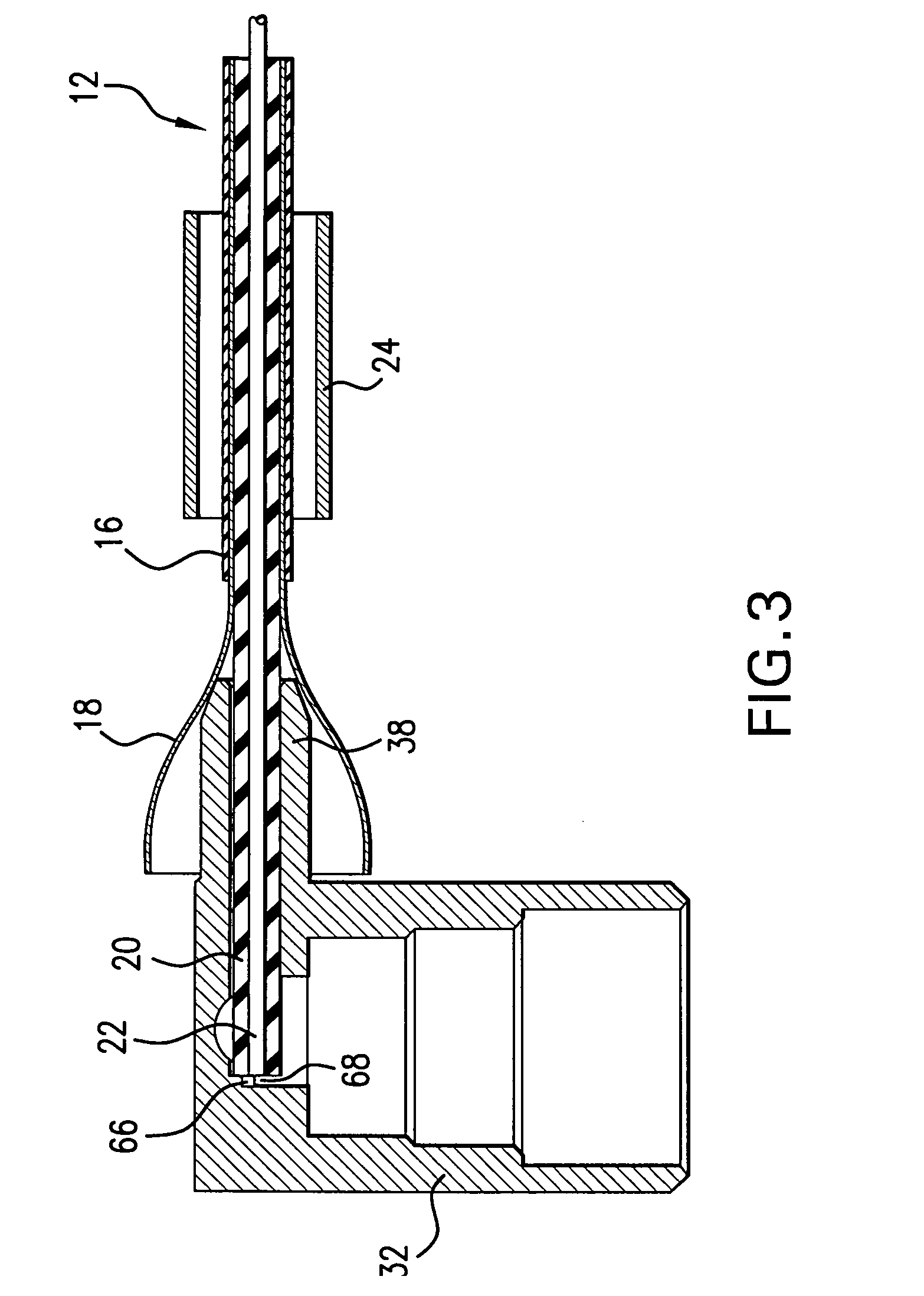
[0036]Referring now to FIG. 1, a coaxial cable 12 has an end 14 prepared for termination to a right angle coaxial cable connector according to the current invention. An outer insulative jacket 16 of the cable is stripped back a predetermined distance and then an outer conductive sheath or braid 18 is exposed and cut back a second, specific distance from the end 14. An inner insulation layer 20 and center conductive core 22 are left undisturbed. A ferrule 24, fashioned from a ductile, electrically conductive material such as brass, is slid over the cable end to surround the outer jacket 16 adjacent the cable end. Then the braid 18 is flared outward.

[0037]A connector body or housing 30 according to the present invention is shown in FIG. 2. The housing may be die-cast from an electrically conductive metal or material such as zinc or a zinc-aluminum alloy. The connector housing 30 has a generally hollow, cylindrical, first main section 32 with a first, open, terminal mating end 34 and a...


PUM


Abstract

A right-angle coaxial cable connector has an inner cable stop for positioning an end of a coaxial cable in a specific location within an electrically conductive connector housing. A terminal device of the connector includes a center contact terminal with insulation displacement blades on one end. A dielectric member is sandwiched between the center contact terminal and an outer electrical contact. The cable stop surface may be a direct projection from the housing or an extension of the dielectric member. The projection or dielectric member electrically isolates a conductive core of the cable from the connector housing. Full insertion of the terminal device or a part of the terminal device into the connector housing causes the blades to cut through insulation of the cable and electrically connect the conductive core of the cable with the center contact terminal. The structure of the connector housing and the assembly process enable inspection of the cable end location within the housing prior to termination of the cable. A ferrule is used to secure the cable to the housing after confirmation of the location. The outer electrical contact of the terminal device is electrically connected to an outer conductive sheath of the cable through the connector housing when the ferrule is crimped on the housing around the sheath.

Description

BACKGROUND OF THE INVENTION[0001]1. Field of the Invention[0002]The invention is directed in general to an angled coaxial cable connector and more specifically to such a connector that makes use of an insulation displacement termination method to minimize assembly time and connector size.[0003]2. Discussion of Related Art[0004]Coaxial cable connectors often have a right-angle, or some other angle, design to facilitate electrical engagement with connection ports or printed circuit boards. This can eliminate the need to significantly bend the cable, and thereby possibly damage the connection between the connector and cable, when making the electrical engagement. Typical right-angle coaxial cable connectors use traditional methods of terminating the cable in the connector such as soldering and crimping. Both have advantages and disadvantages. In the soldering method, the size of the connector can be relatively small because the cable is brought in perpendicular to an axis of the interf...

Claims


Application Information

Patent Timeline
IPC IPC(8): H01R9/05
CPCH01R9/053H01R24/40H01R2103/00
Inventor ZEREBILOV, ARKADY Y.SHELLY, CHRISTOPHER W.FUKASE, YOSHIHIRO
Owner YAZAKI NORTH AMERICA
Why Eureka
Try Eureka