MEMS scanner with dual magnetic and capacitive drive

a magnet and capacitive drive technology, applied in the field of microelectromechanical system devices, can solve problems such as image distortion, overlap of pixels, and gap between adjacent rows of pixels

Active Publication Date: 2006-07-04
MICROVISION
View PDF19 Cites 114 Cited by
  • Summary
  • Abstract
  • Description
  • Claims
  • Application Information

AI Technical Summary

Problems solved by technology

This uneven spacing can cause the pixels to overlap or can leave a gap between adjacent rows of pixels.
Moreover, because the image information is typically provided as an array of data, where each location in the array corresponds to a respective position in the ideal raster pattern 70, the displaced pixel locations can cause image distortion.
Consequently, a large mirror and larger scan angle may produce unacceptable refresh rates for many MEMS scanners.

Method used


Image

  • MEMS scanner with dual magnetic and capacitive drive
  • MEMS scanner with dual magnetic and capacitive drive
  • MEMS scanner with dual magnetic and capacitive drive

Examples


Embodiment Construction

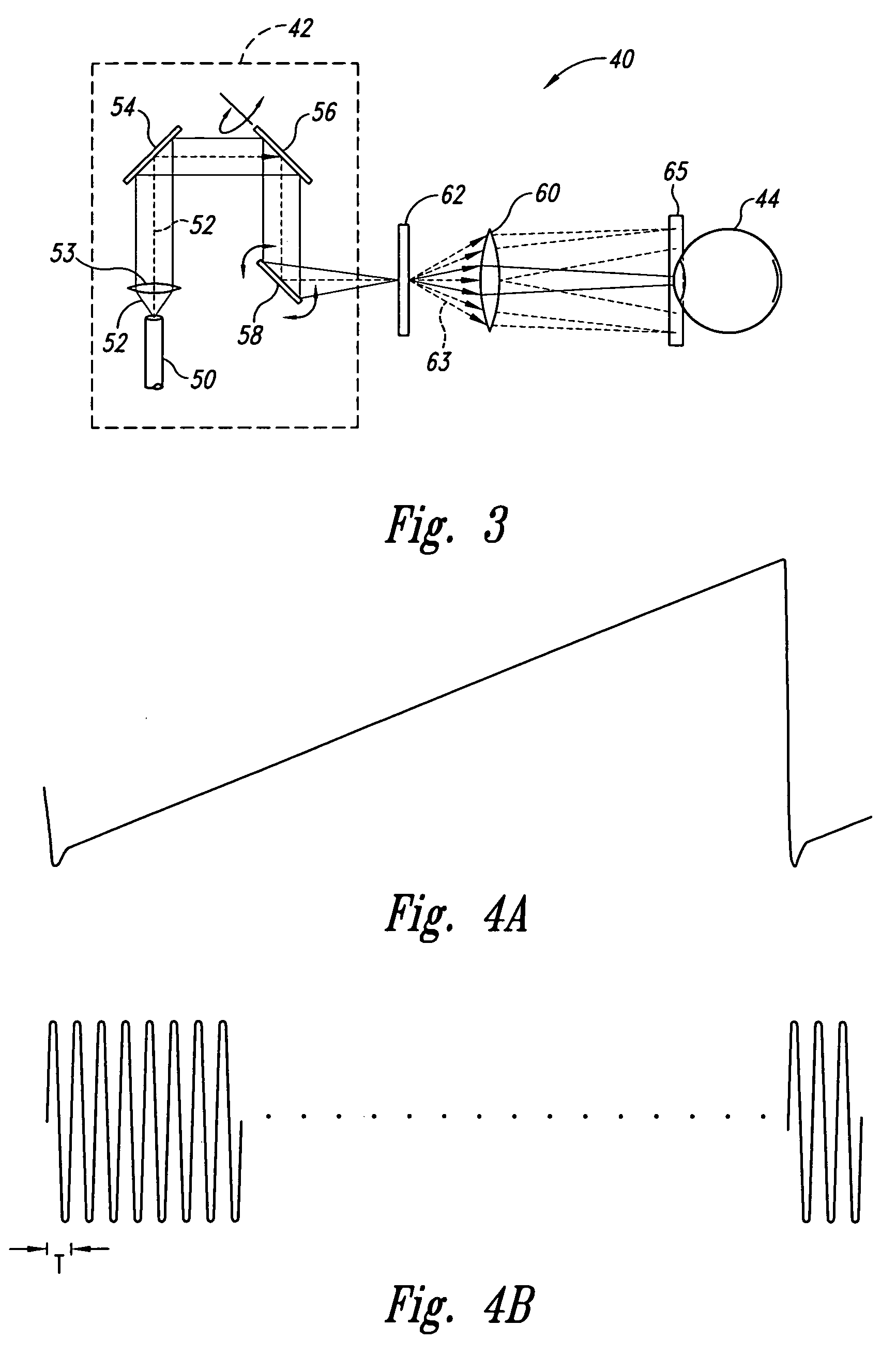
[0070]As shown in FIG. 6, a scanned beam display 40 according to one embodiment of the invention is positioned for viewing by a viewer's eye 44. While the display 40 is presented herein as scanning light into the eye 44, the structures and concepts described herein can also be applied to other types of displays, such as projection displays that include viewing screens, as well as other types of scanning apparatuses.

[0071]The display 40 includes four principal portions, each of which will be described in greater detail below. First, control electronics 74 provide electrical signals that control operation of the display 40 in response to an image signal VIM from an image source 76, such as a computer, television receiver, videocassette player, DVD player, remote sensor, or similar device.

[0072]The second portion of the display 40 is a light source 50 that outputs modulated light beams 52, each having a modulation corresponding to information in the image signal VIM. The light source 5...


PUM


Abstract

A MEMS scanning device includes more than one type of actuation. In one approach capacitive and magnetic drives combine to move a portion of the device along a common path. In one such structure, the capacitive drive comes from interleaved combs. In another approach, a comb drive combines with a pair of planar electrodes to produce rotation of a central body relative to a substrate. In an optical scanning application, the central body is a mirror. In a biaxial structure, a gimbal ring carries the central body. The gimbal ring may be driven by more than one type of actuation to produce motion about an axis orthogonal to that of the central body. In another aspect, a MEMS scanning device is constructed with a reduced footprint.

Description

[0001]This application claims benefit of Provisional application Ser. No. 60 / 423,584 filed Nov. 4, 2002.TECHNICAL FIELD[0002]The present invention relates to microelectromechanical system (MEMS) devices and, more particularly, to MEMS devices with motive forces.CROSS REFERENCES TO RELATED APPLICATIONS[0003]The present application depends from Provisional Patent Application No. 60 / 423,584 entitled MEMS DRIVE STRUCTURES, by Yan et al., filed Nov. 4, 2002.BACKGROUND OF THE INVENTION[0004]A variety of approaches to actuating MEMS devices have been described. Some approaches use magnetic fields to pivot a moving member relative to a substrate. One such approach is described in U.S. Pat. No. 5,912,608 to Asada, entitled PLANAR TYPE ELECTROMAGNETIC ACTUATOR and U.S. Pat. No. 5,767,666 to Asada et al., entitled PLANAR TYPE ELECTROMAGNETIC ACTUATOR INCORPORATING A DISPLACEMENT DETECTION FUNCTION, each of which is incorporated herein by reference. Other approaches use electrostatic forces to ...

Claims


Application Information

Patent Timeline
Patent Type & Authority Patents(United States)
IPC IPC(8): H02N1/00
CPCG02B26/085H02N1/008G02B26/101
Inventor YAN, JUNCASASANTA, III, VINCENZOLUANAVA, SELSO H.UREY, HAKANDEWITT, IV, FRANK A.TEGREENE, CLARENCE T.WIKLOF, CHRISTOPHER A.
Owner MICROVISION
Why Eureka
Try Eureka